ChibiOS powered reflow oven with web interface
It seems, that converting toaster ovens to reflow ovens is quite a popular thing to do and considering, that I might need to solder some QFNs (or even BGAs) some time soon, I decided to take a whack at it too.
In the end, I ended up with an ARM powered board with an Ethernet interface which can we controlled over a nice web UI (and the whole thing has not set the house on fire, yet).

Components
The toaster oven — Adler AD-6003
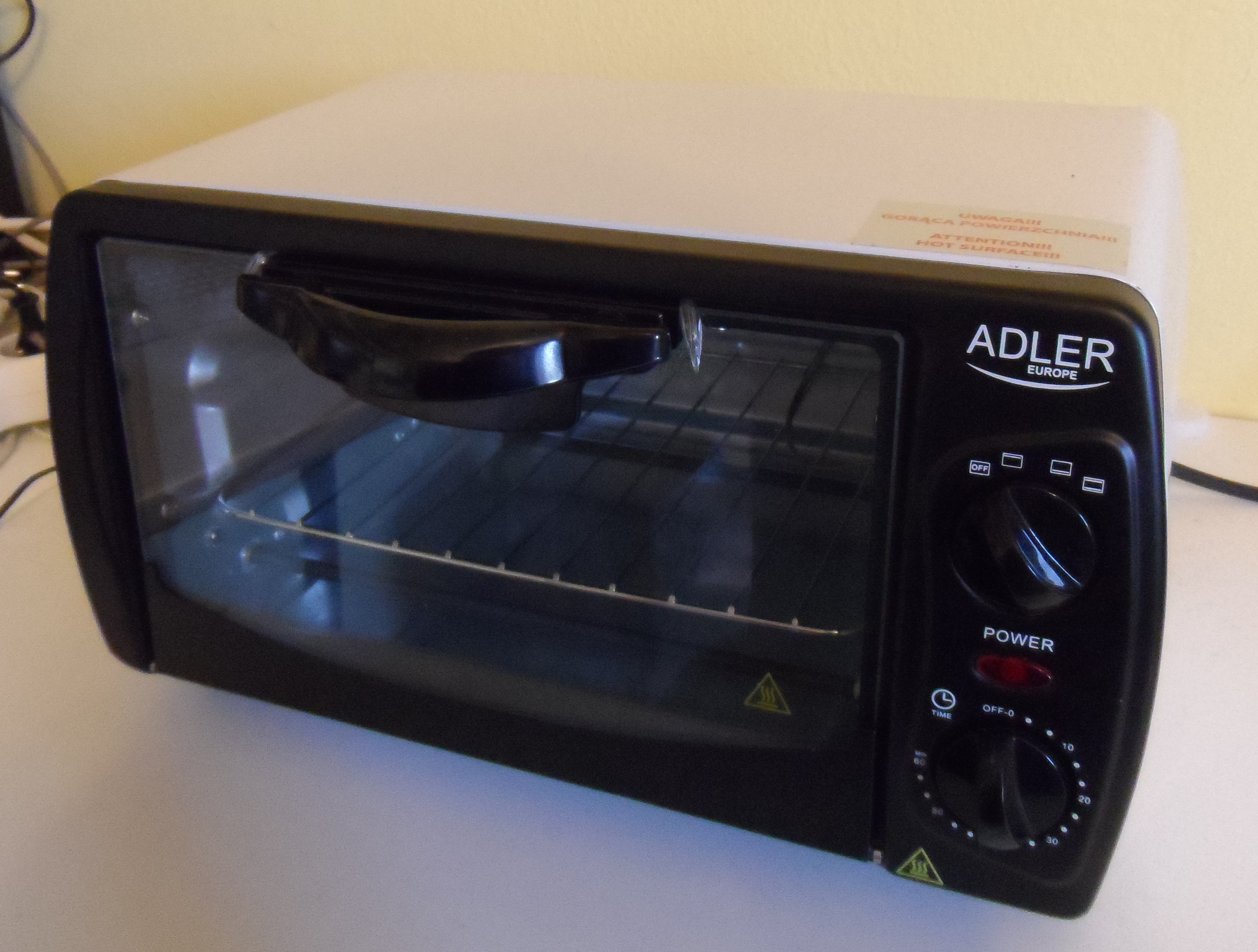
This was one of the cheapest ovens I could buy (~30$). It does have two pairs of heating elements, one pair on top and one on bottom which can be individually controlled by a rotary switch on the front panel. The power output is 1kW.
MCU — STM32F030C8T6
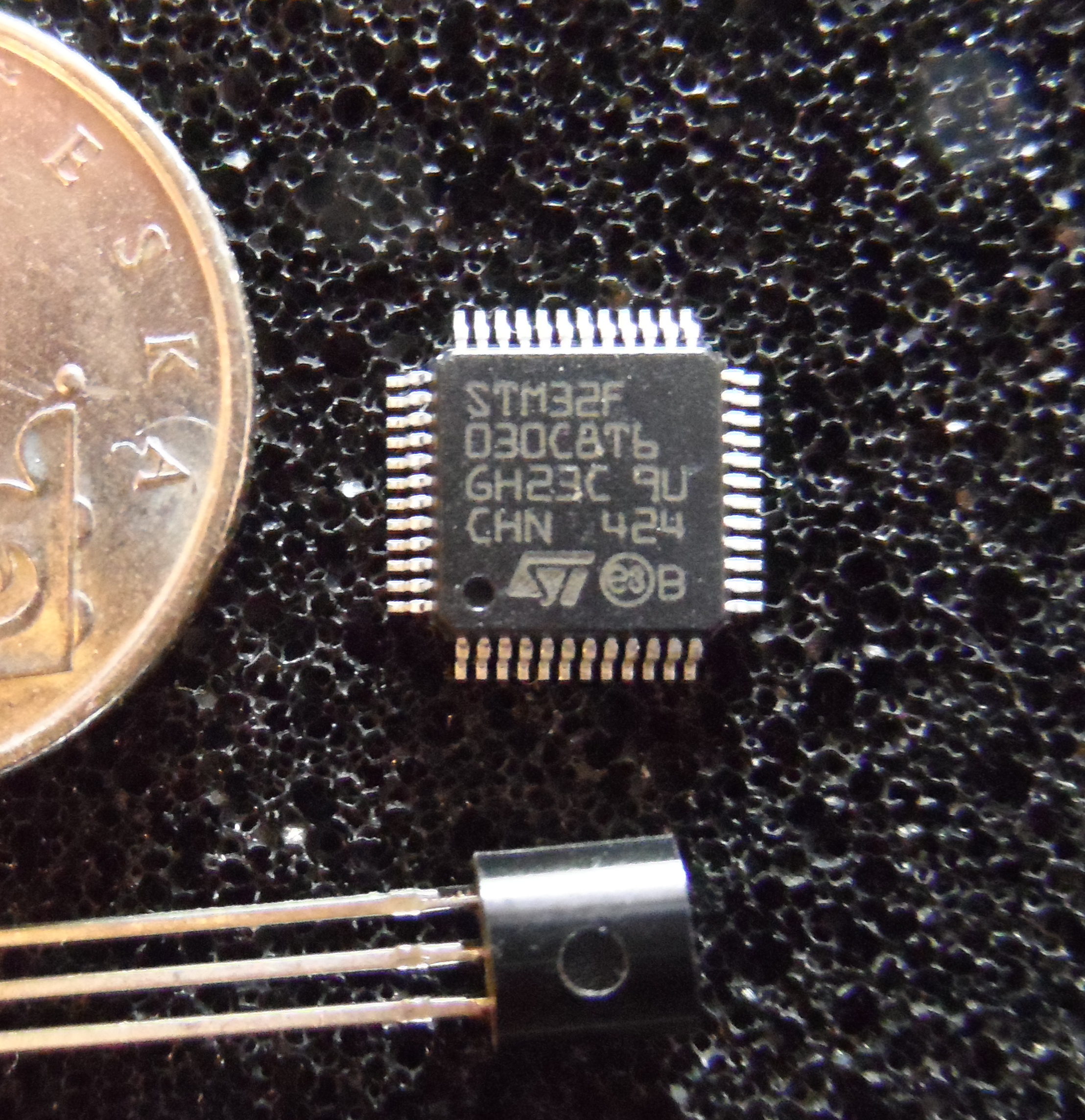
This is a low-end ARM microcontroller made by ST as a part of their STM32 line. When compared to the ATmega328p I have used a few times in the past, it is still quite superior and what is better, it is actually cheaper (we can now buy similar but overall better 32bit ARM for less than an 8bit AVR, welcome to the future).
| STM32F030C8T6 | |
| Architecture | ARM Cortex-M0 |
| Max. clock rate | 48 MHz |
| Operating Voltage | 2.4V - 3.6V |
| Flash | 64kB |
| RAM | 8kB |
| ADC | 1 (12 Channels) |
| SPI | 2 |
| I²C | 2 |
| USART | 2 |
| GPIO | 39 |
| Package | LQFP48 |
| Price | $ 1.85 |
Oven temperature sensor — MAX6675
This is a single chip solution for measuring high temperatures. The chip contains an amplifier, cold-junction compensation, ADC and SPI interface. It uses common K-type thermocouples and is able to measure with a resolution of 0.25 °C. Note that these are deprecated and have been replaced by the more advanced MAX31855. They can still be relatively cheaply purchased on eBay though.
On-board temperature sensor — LM75AD
To add some extra protection, so the software can shutdown the heating elements if the board is overheating (or is on fire…) I wanted to have a way of measuring the temperature on the PCB itself. The LM75 sensors is somewhat of an industry standard and there are dozens of different derivatives with varying parameters.
Ethernet — ENC28J60 and J0026D21BNL
The ENC28J60 is a popular Ethernet controller for small MCUs which interfaces with the host over SPI.
The J0026D21BNL is a MagJack — this means that it is an Ethernet connector which does have the 1:1 isolation transformers needed for the two Ethernet differential pairs integrated and therefore they do not need to be as a discrete parts on the board.
I have used both of these parts before and had a few pieces left over, so they were an obvious choice.
SSR Relays — Fotek SSR25
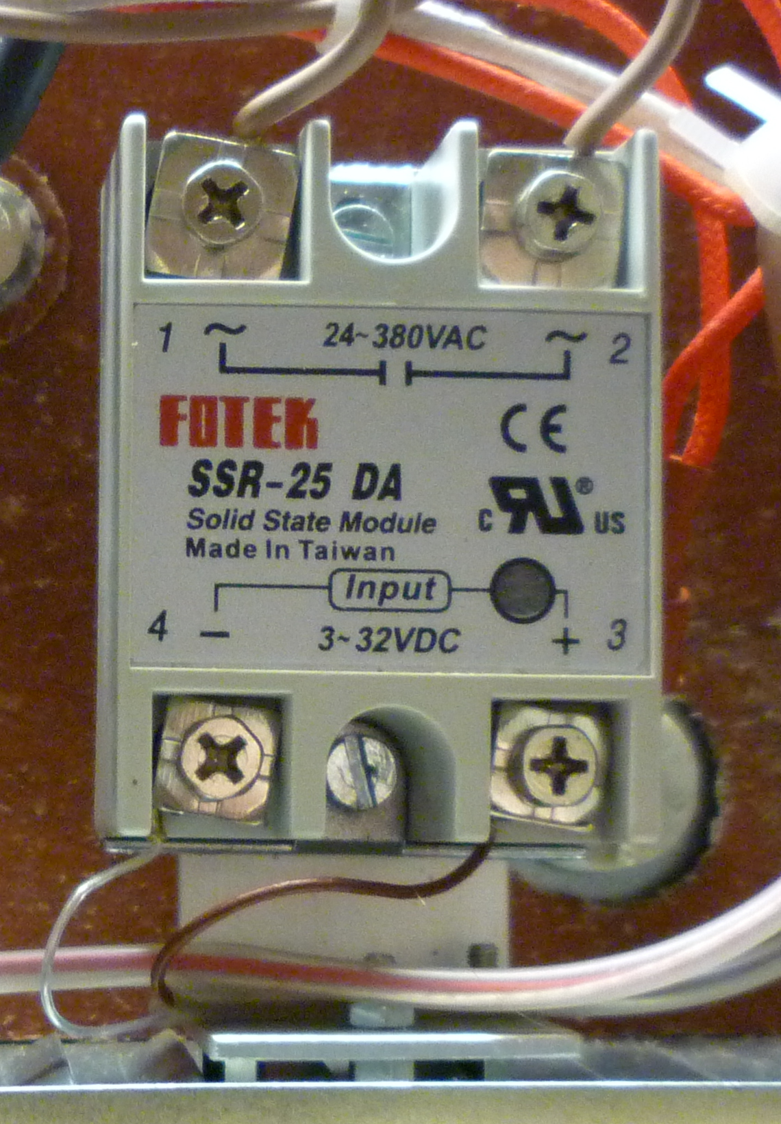
To control the heating elements, some relays are needed. The ones I used can be bought from eBay for around 4$ a piece. They should be able to switch up to 380VAC at 25A (would not trust them at this load, they are still cheap relays) and the minimal control voltage is 2.4V (this showed to not be true, but more on that later). As one would expect, they also feature
PCB
First, the schematic:

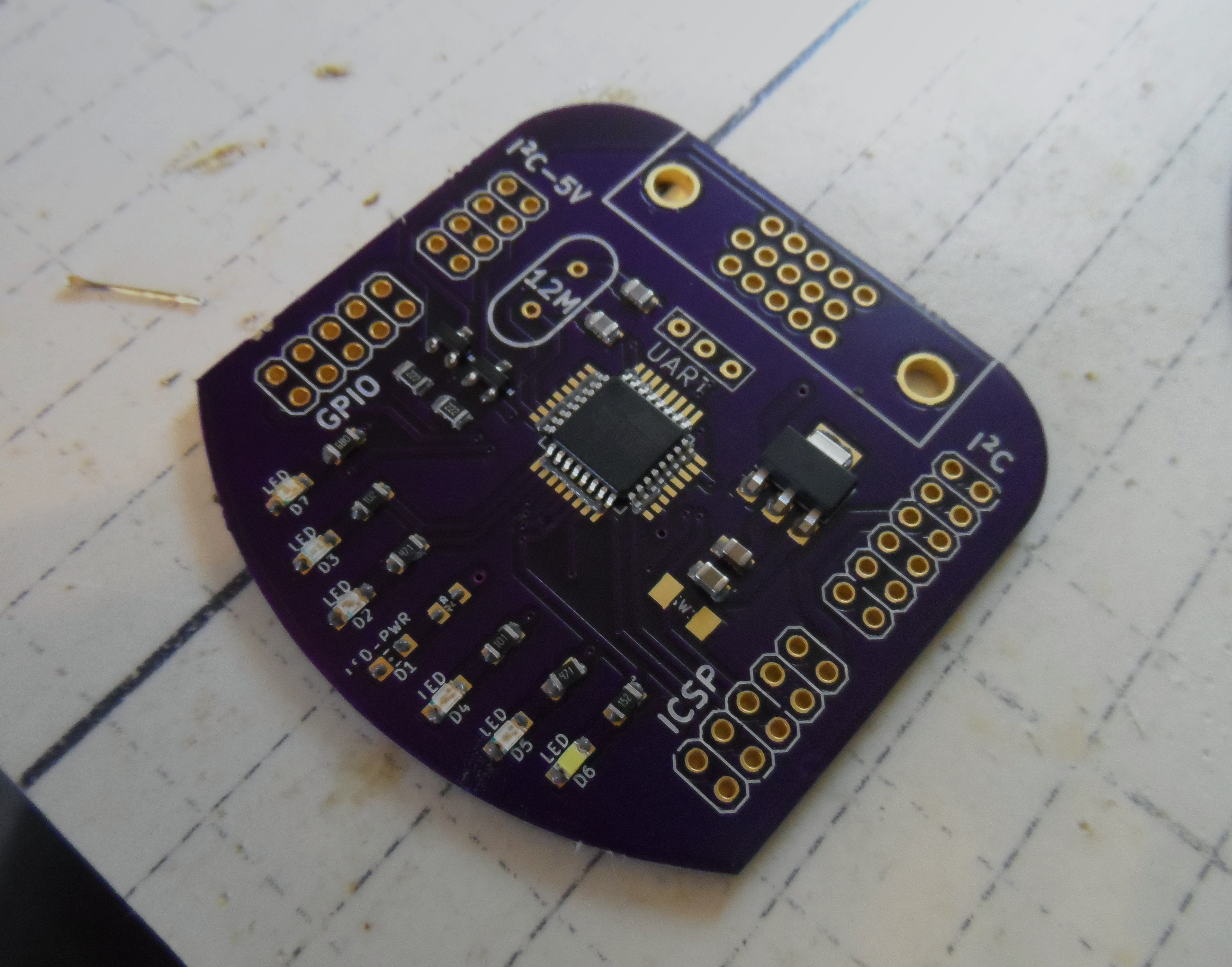
And then the board:
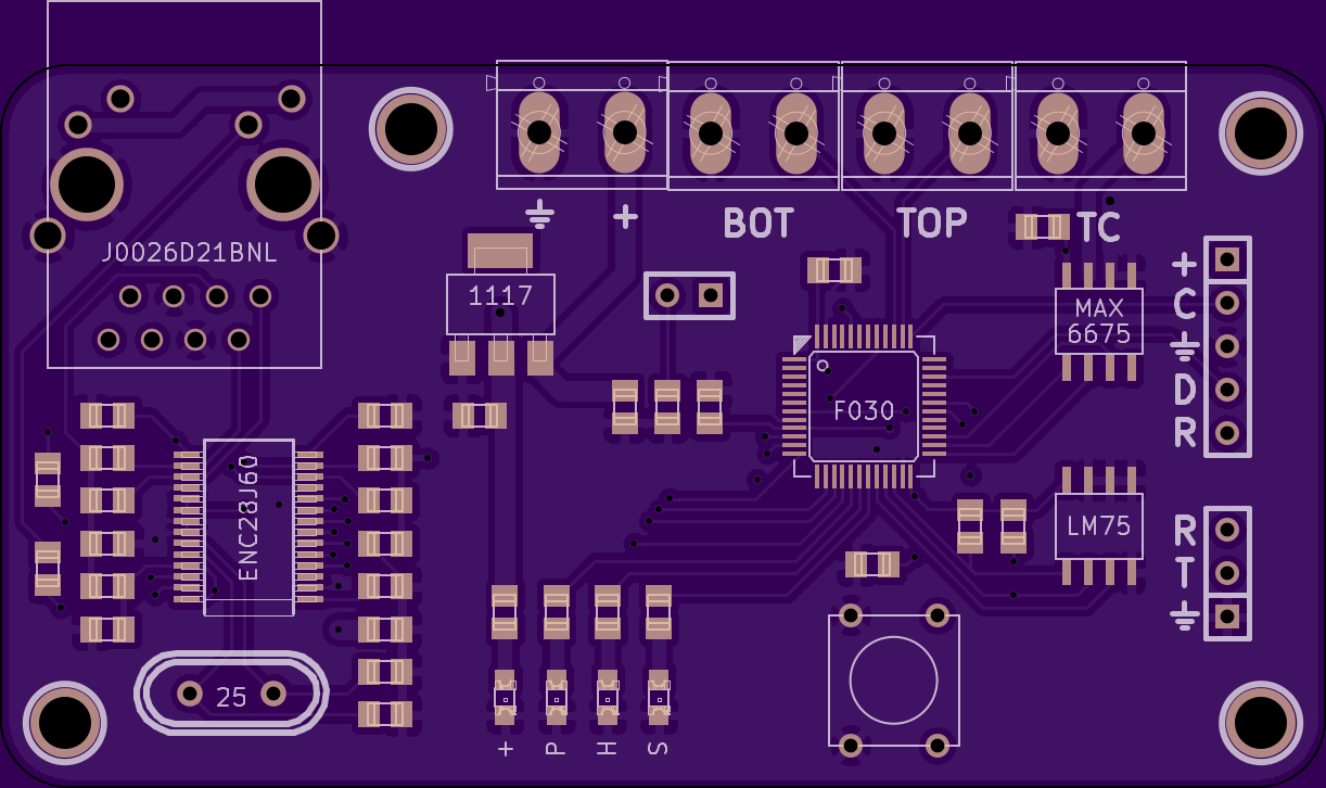
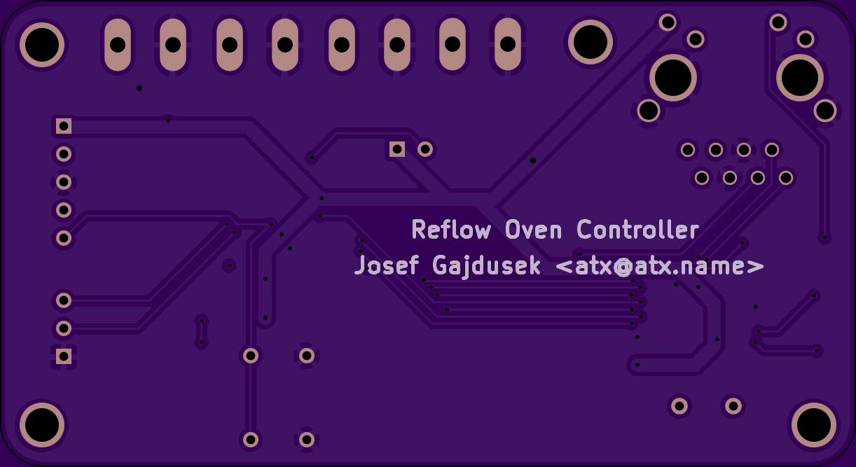
So, in list form:
- 8 screw terminals:
Unregulated Vin + -, Bottom relay + -, Top relay + -, Thermocouple + - - The AMS1117 LDO, which can theoretically handle up 15V input
- SWD programming header with Nucleo-compatible pinout
- UART Header
- Hardware reset button
- Four M3 mounting holes
- BOOT0 jumper header — this is useful if one manages to misconfigure the SWD pins
- Four LEDs — One tied to 3.3V, other three controllable by the MCU
- ENC28J60 is connected to SPI1
- MAX6675 to SPI2
- LM75 to I2C1
And the final BoM is:
| Component | Amount | Price |
| STM32F030C8T6 | 1 | $ 1.85 |
| J0026D21BNL | 1 | $ 1.45 |
| ENC28J60 | 1 | $ 1.90 |
| MAX6675 | 1 | $ 3.50 |
| LM75AD | 1 | $ 0.60 |
| AMS1117 | 1 | $ 0.10 |
| Some 2.54mm headers and screw terminals | - | - |
| A bunch of passives | - | - |
| LED | 4 | - |
| 25MHz Crystal | - | - |
| PCB | 1 | $ 8.50 |
| PCB Subtotal | $ 17.90 | |
| Fotek SSR-25 | 2 | $ 8.00 |
| K-type thermocouple | 1 | $ 2.50 |
| Oven | 1 | $ 30.00 |
| Some wires | - | - |
| Screws, standoffs... | - | - |
| $ 58.40 |
Note: Most parts were bought in 5-10 pieces quantities, which means that I paid more for the project than the per-unit total in the BoM
Build
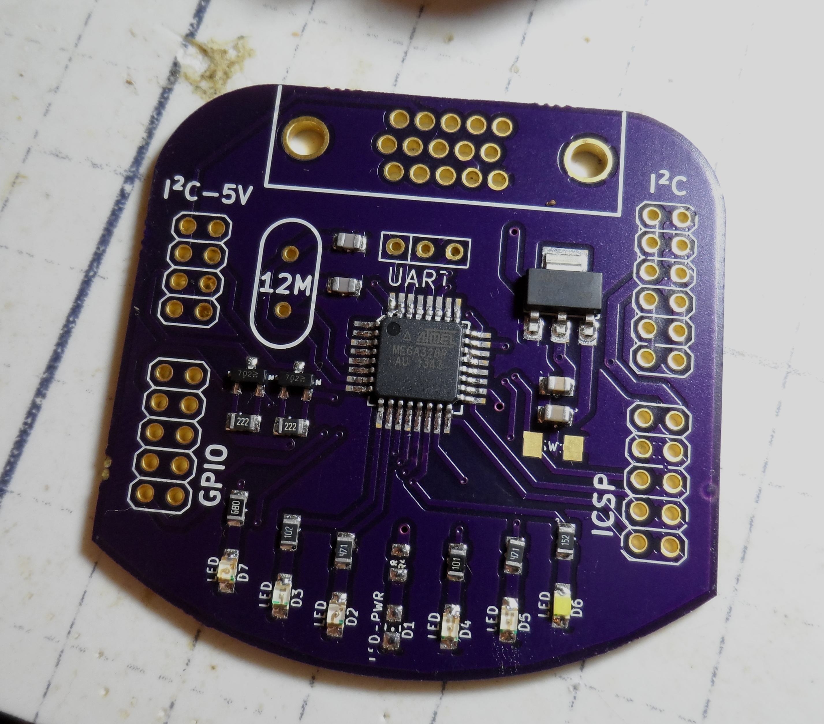
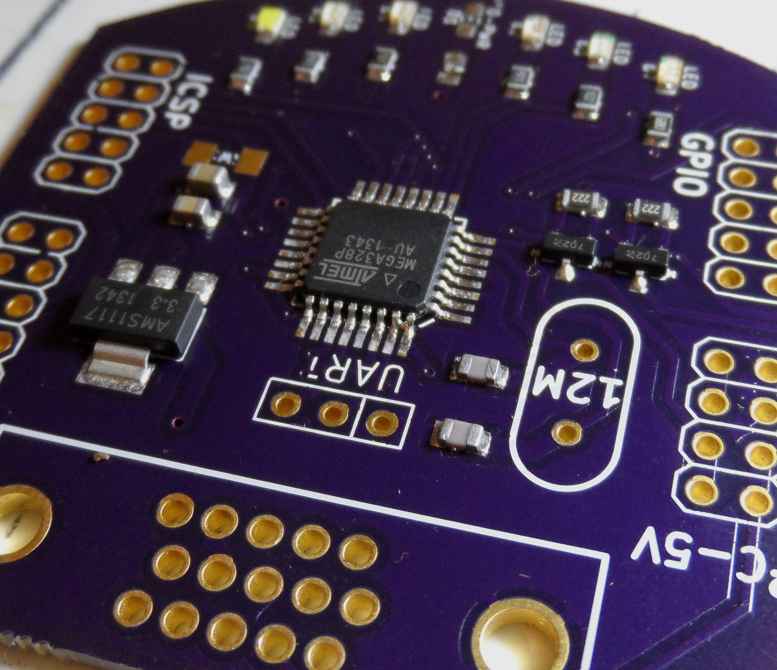
After few weeks, the boards arrived from OSHPark (this was the rare point at which cost of a batch from DirtyPCBs and OSHPark intercepts so I figured I would go for the higher quality option).
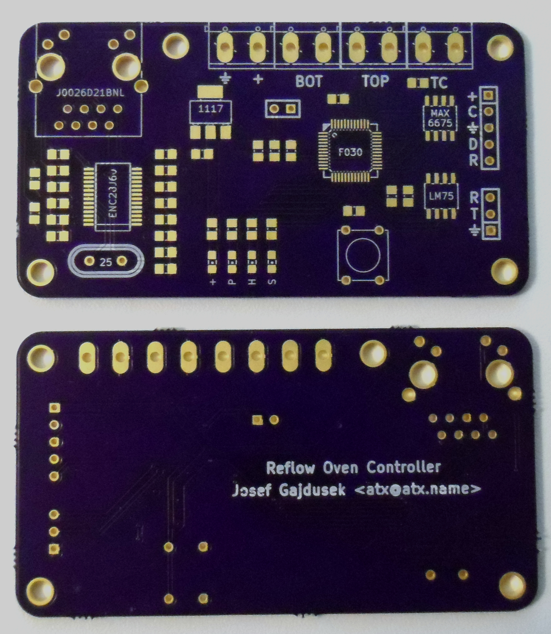
Now off to soldering. I took somewhat of a risk using the LQFP48 ARM because I was not that sure whether these small pin pitch packages are actually

The rest of the components were package sizes I have already soldered in the past.
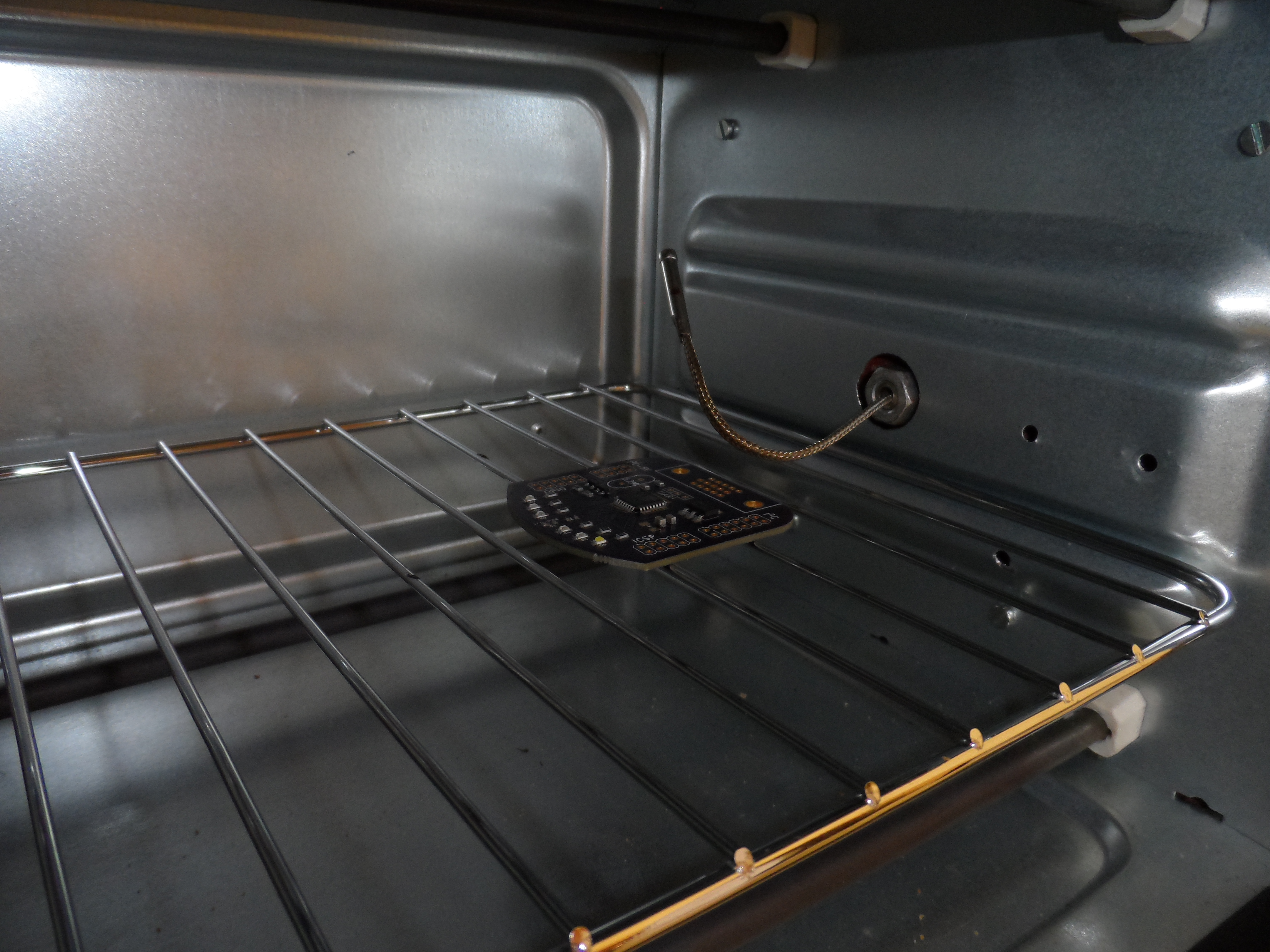
Now to the oven rebuild.
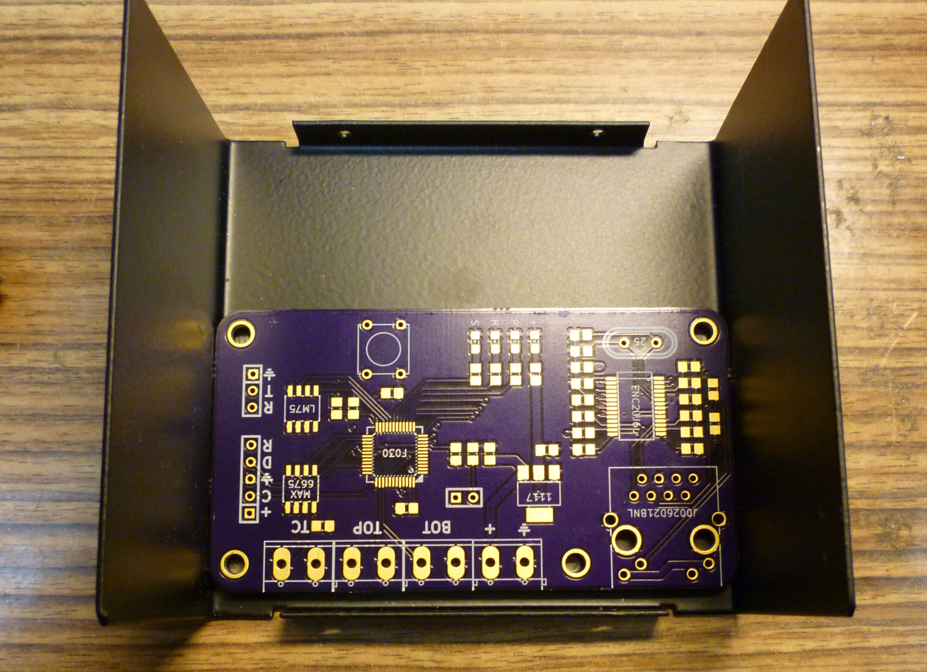
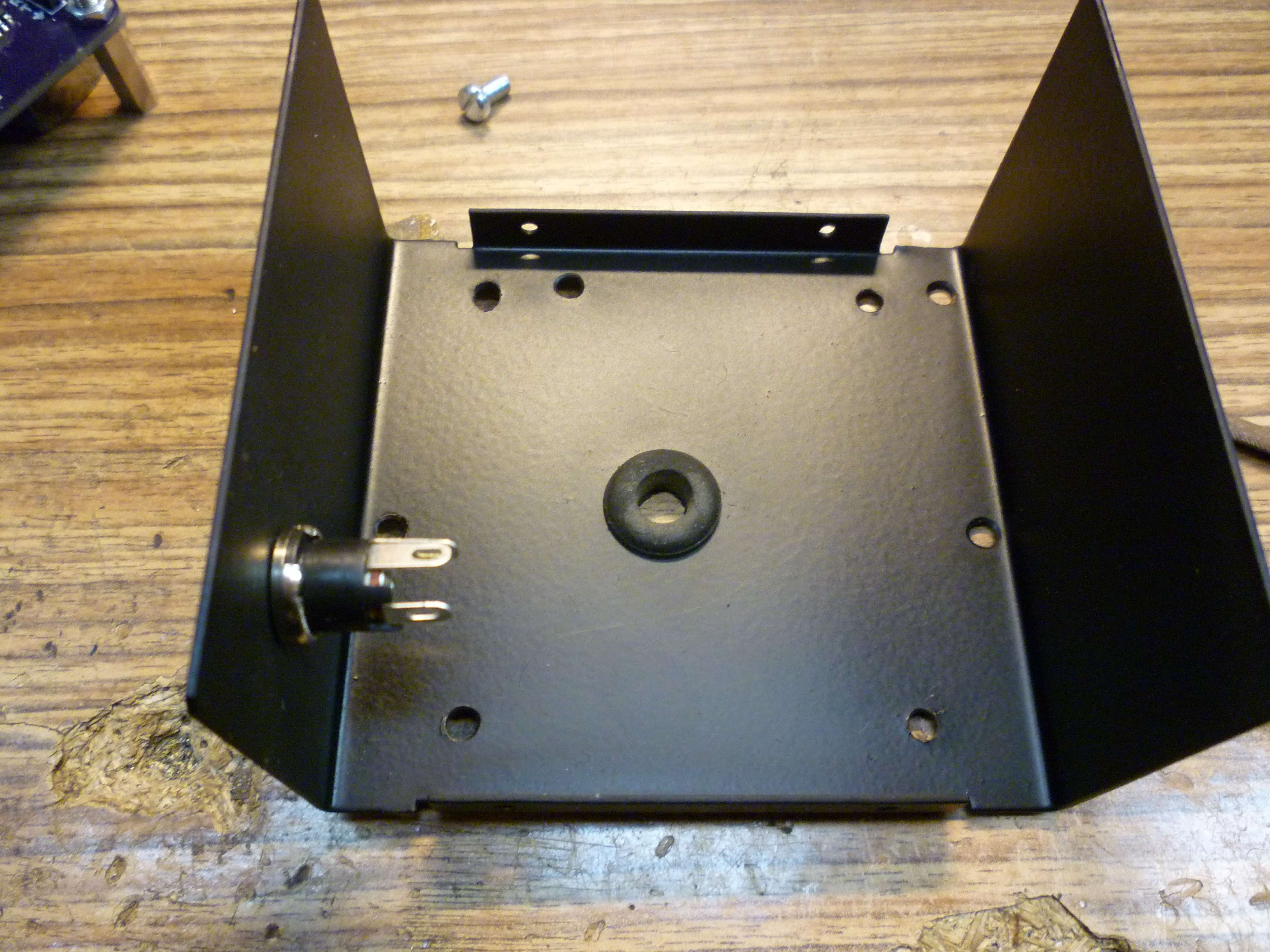
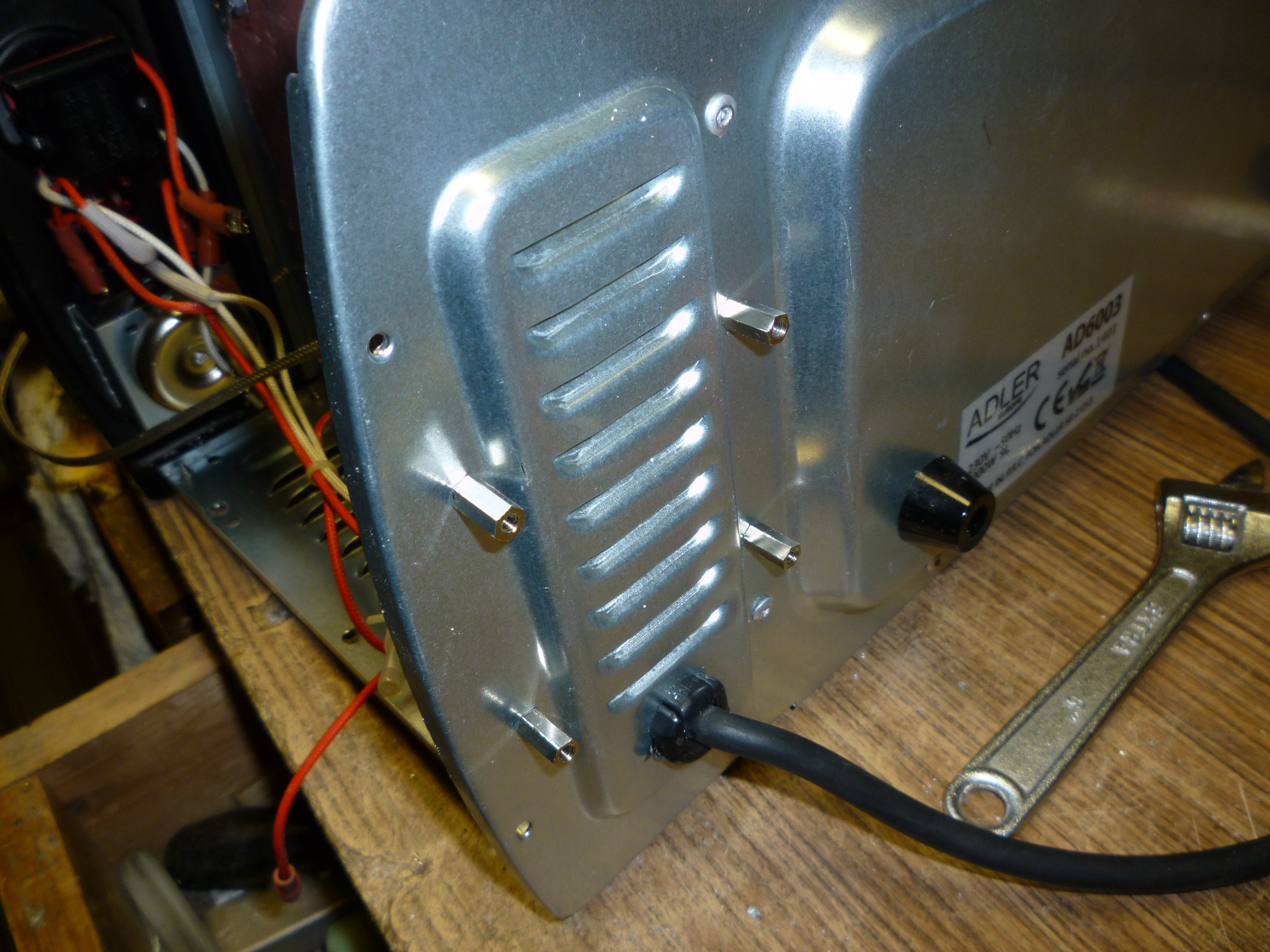
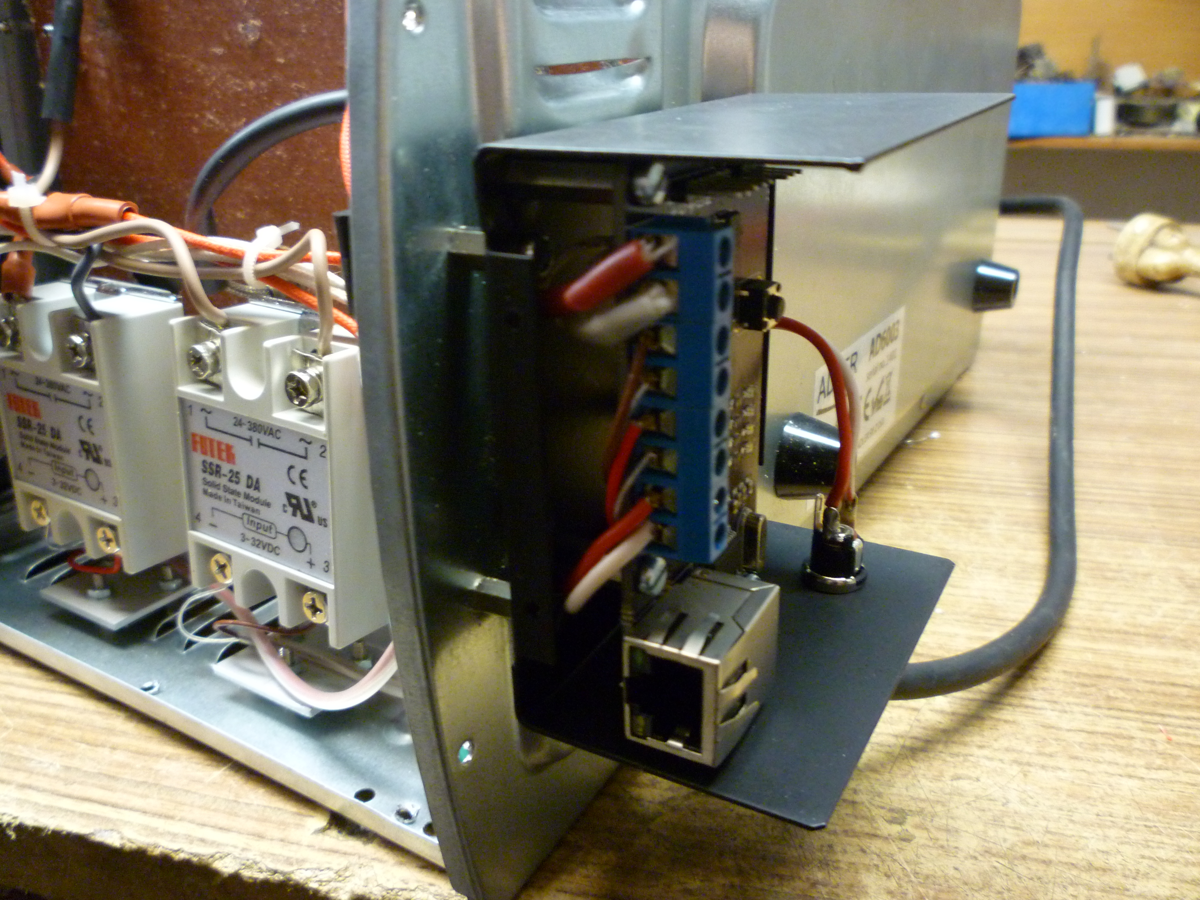
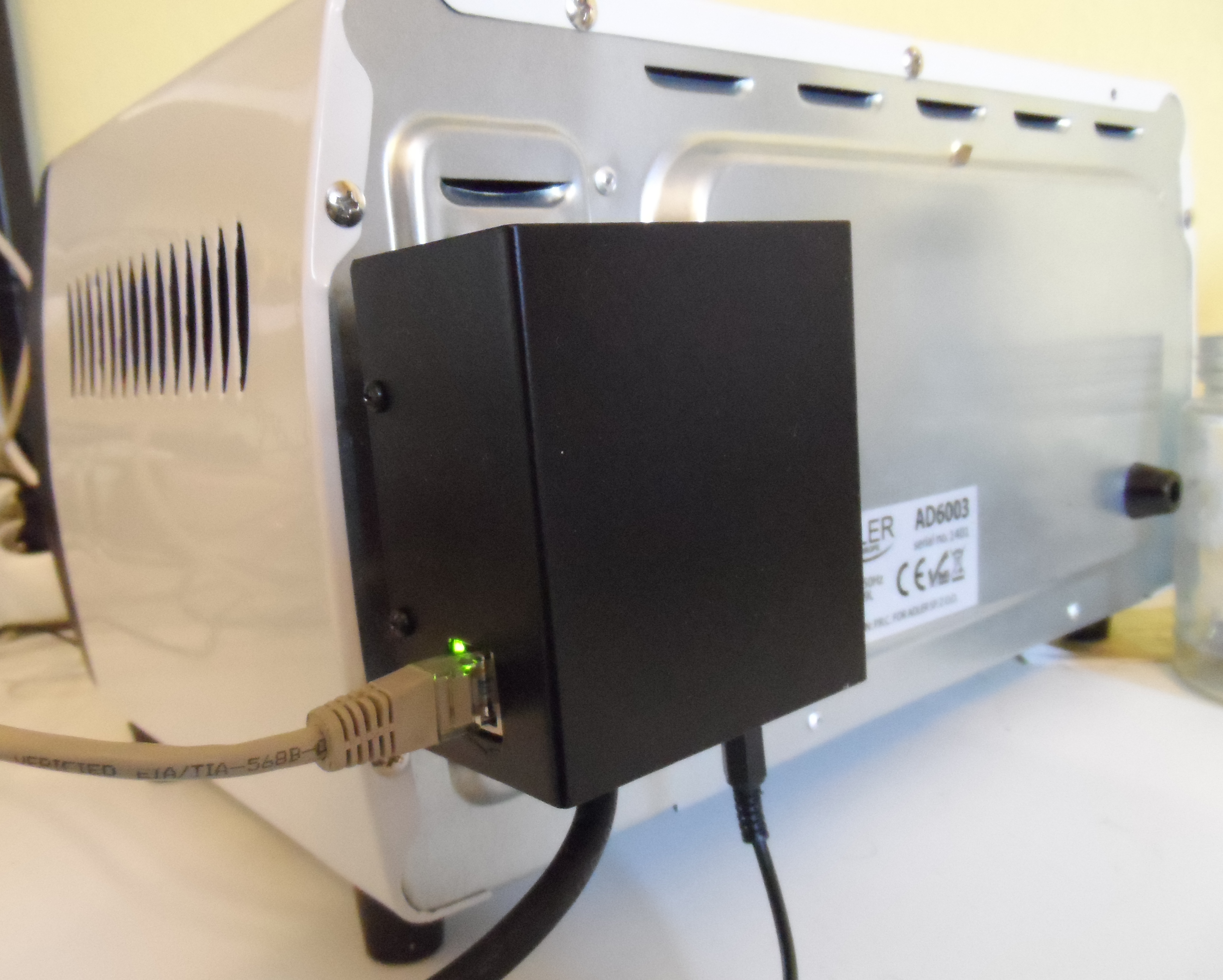
I decided that for safety, ease of access and heat reasons, the controller will be placed outside of the main oven case. So I picked this aluminium
![]()
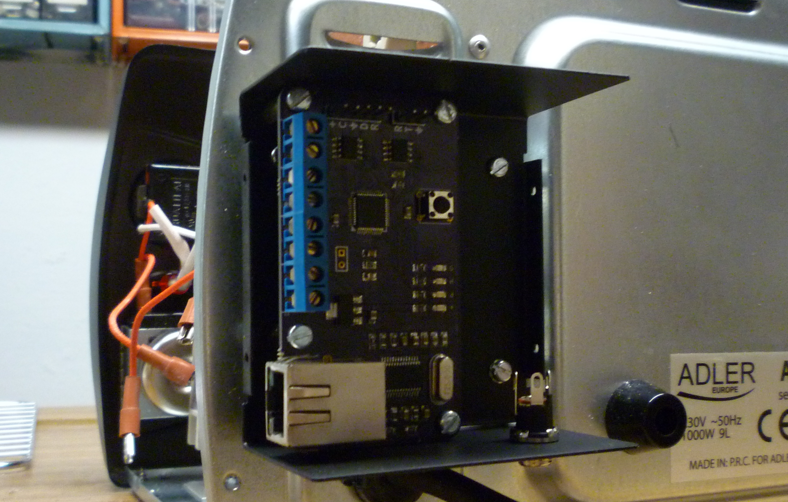
By a chance (and a little bit of filing), the PCB fits perfectly.
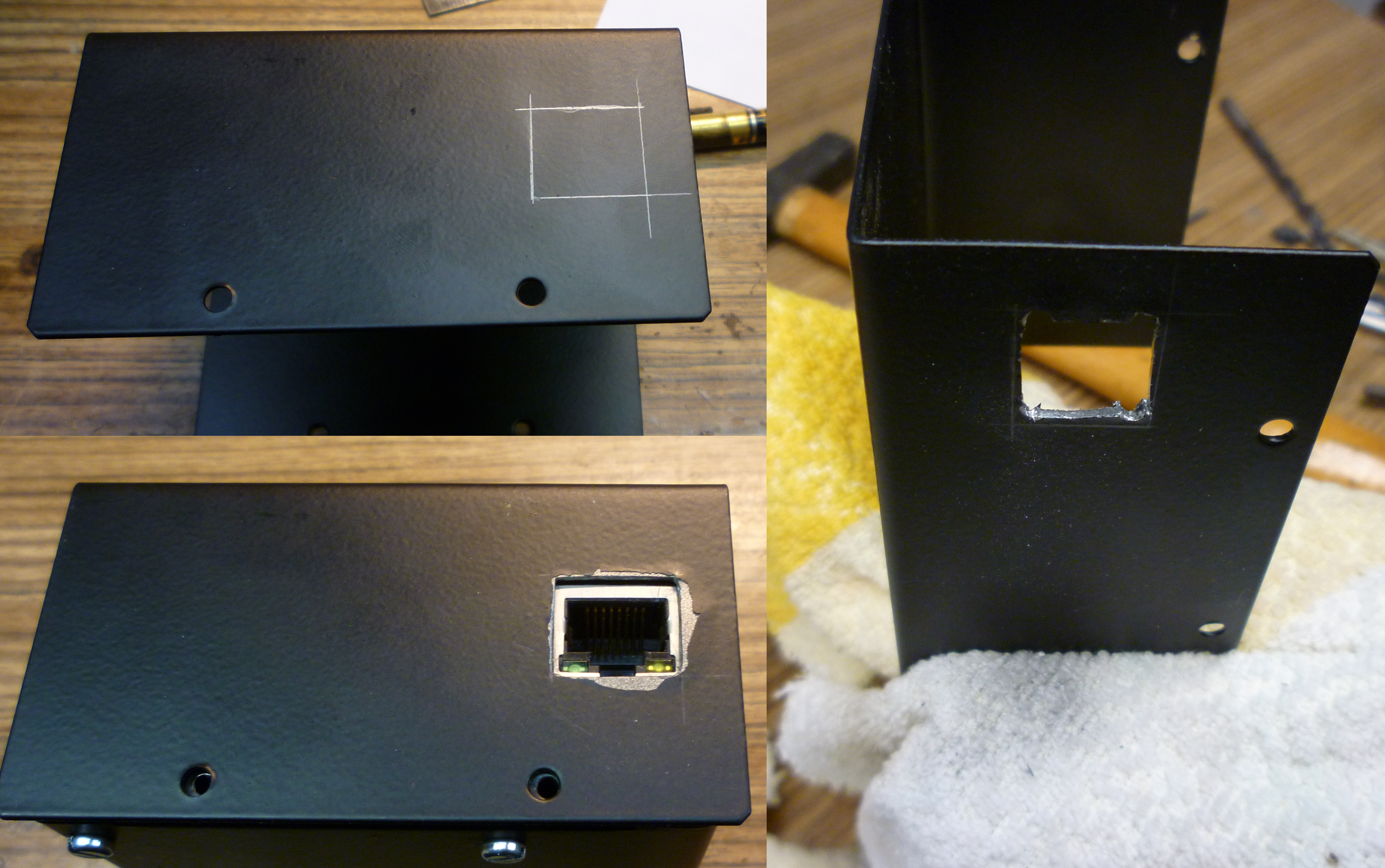
Drill some holes.

And for the Ethernet connector.
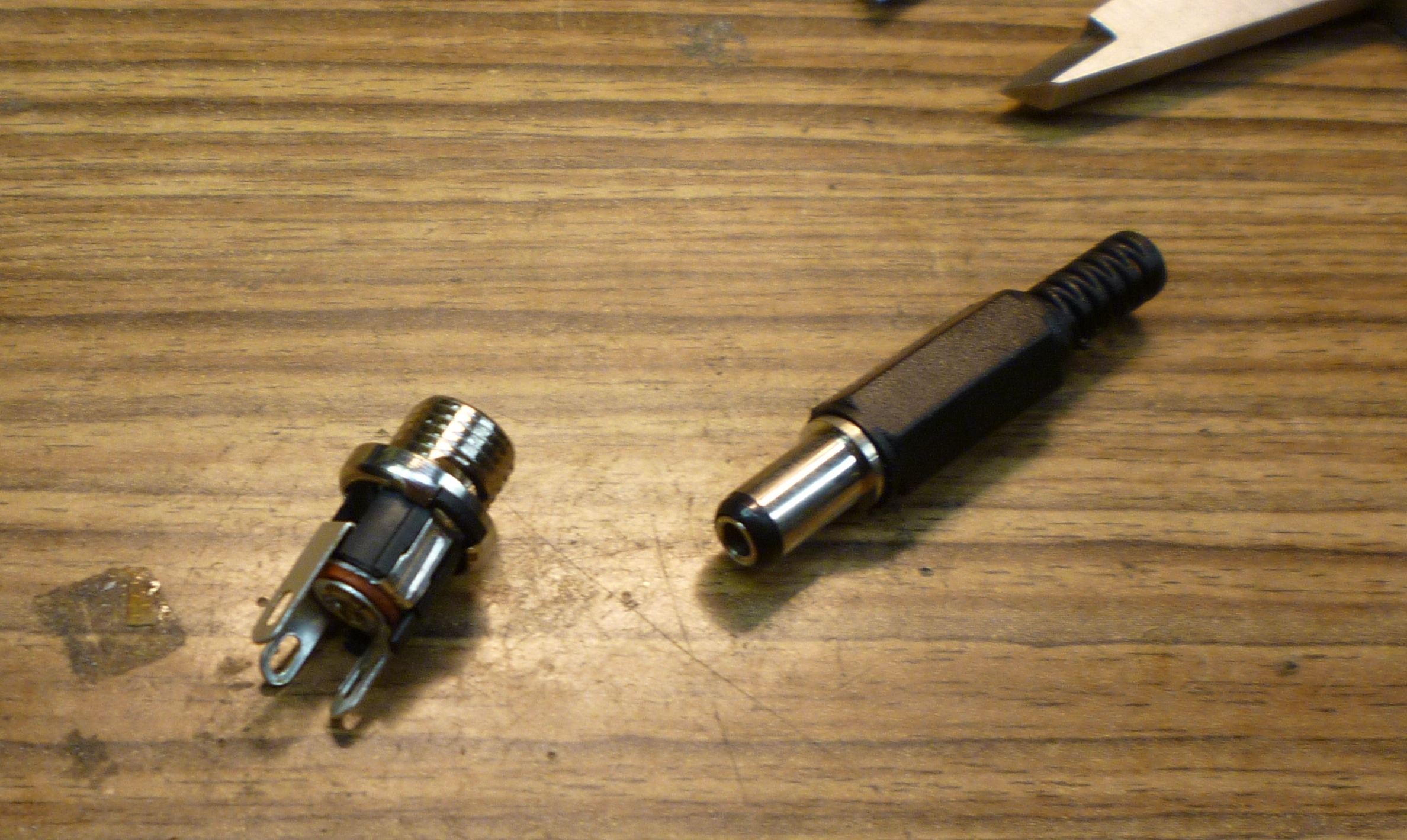
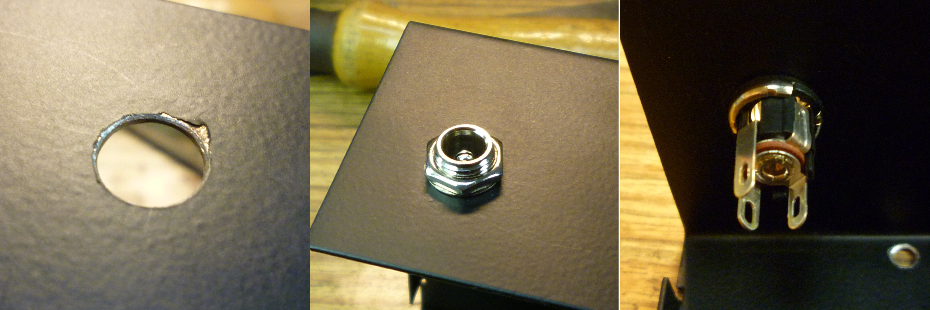
As the controller will be powered from an external 5V plug pack, I also added a 2.1mm power connector.
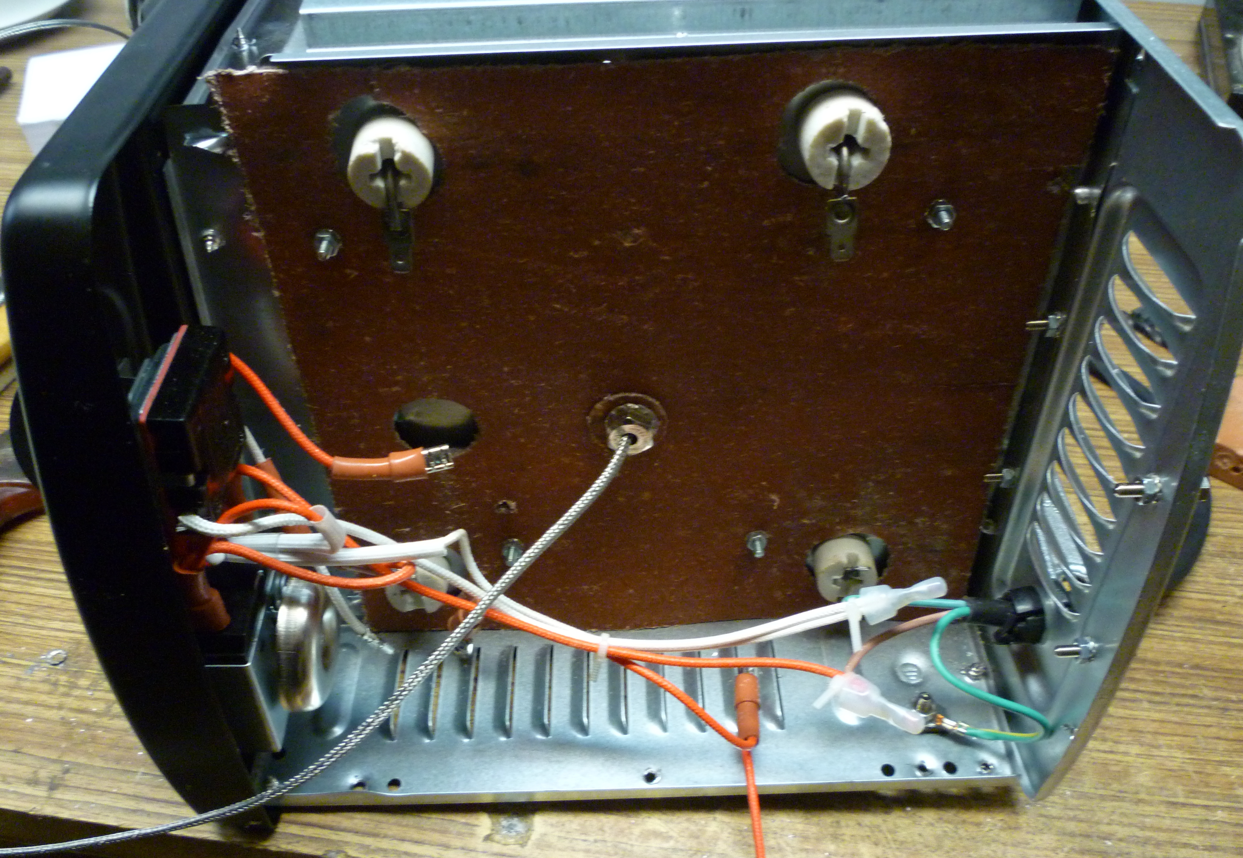
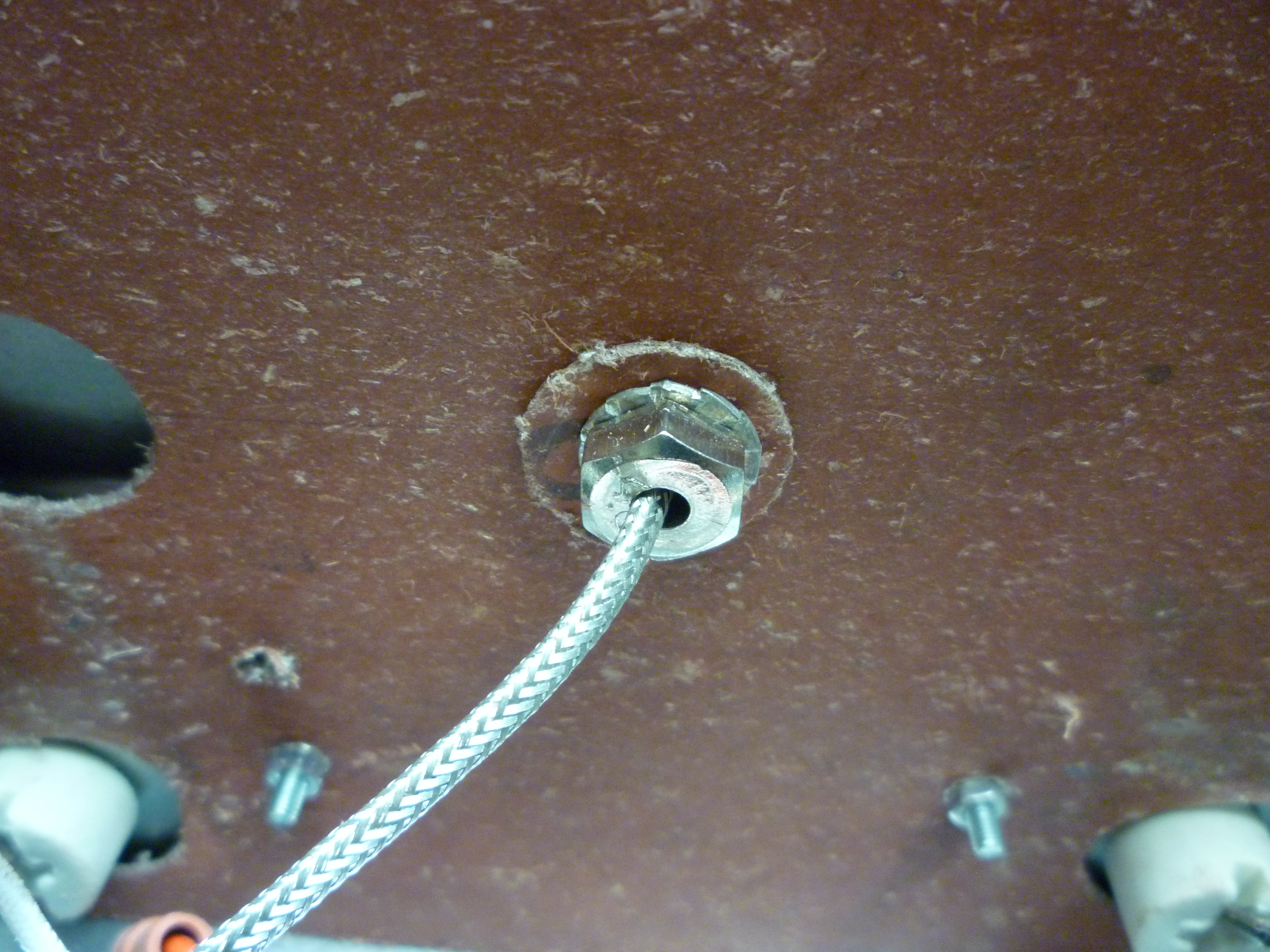
Add hole on the bottom for the relay control wires and the thermocouple.
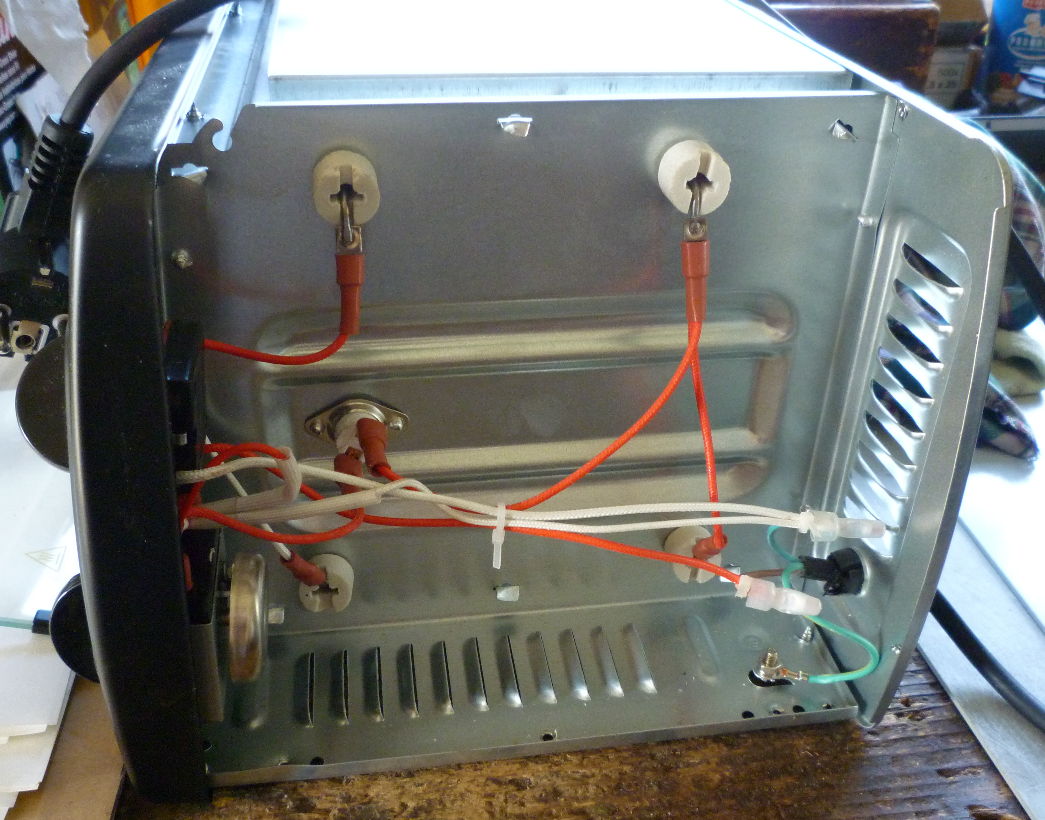
This is the original oven wiring.
Add some heat insulator.
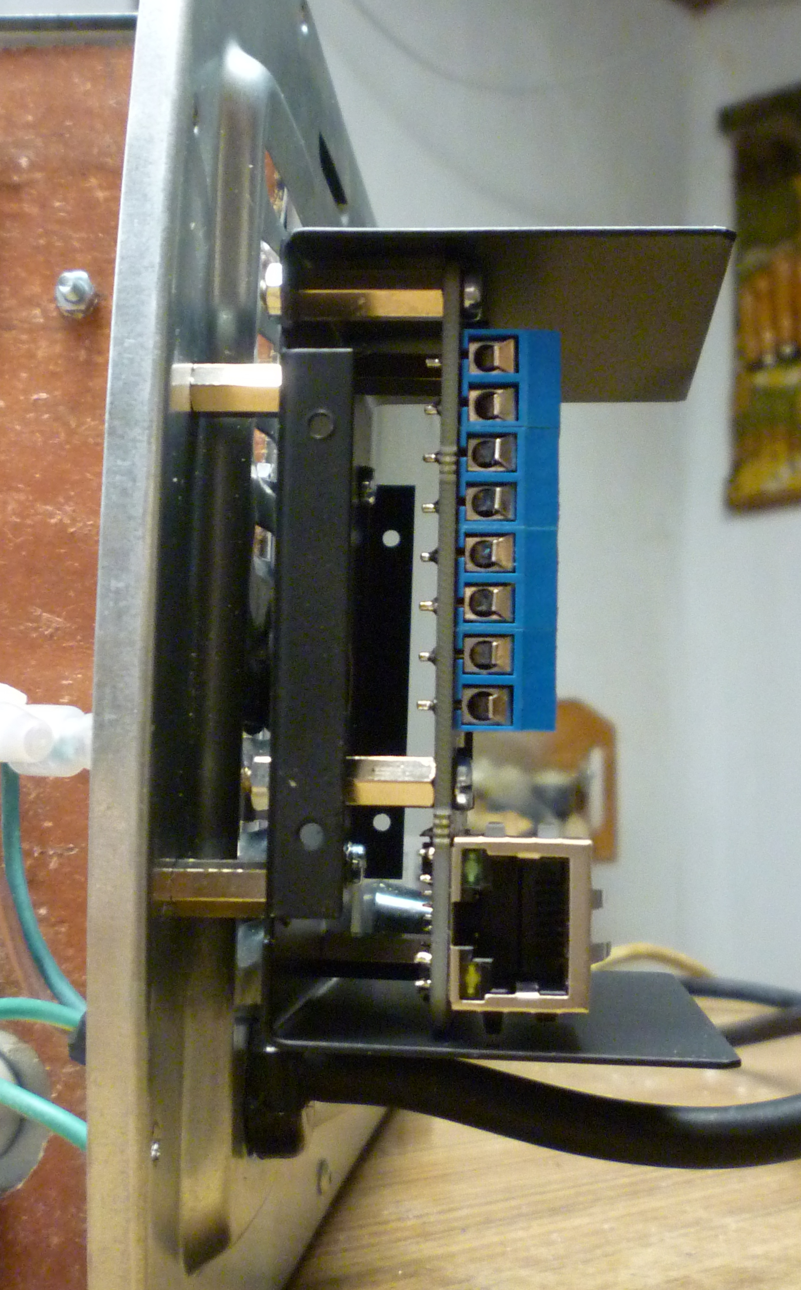
Mount the controller box on brass standoffs.
The relays, mounted on a piece of aluminium.

And finally redo the wiring. The heating elements are connected to the mains power through both the relays and the original hardware switch. The timer is left unconnected.
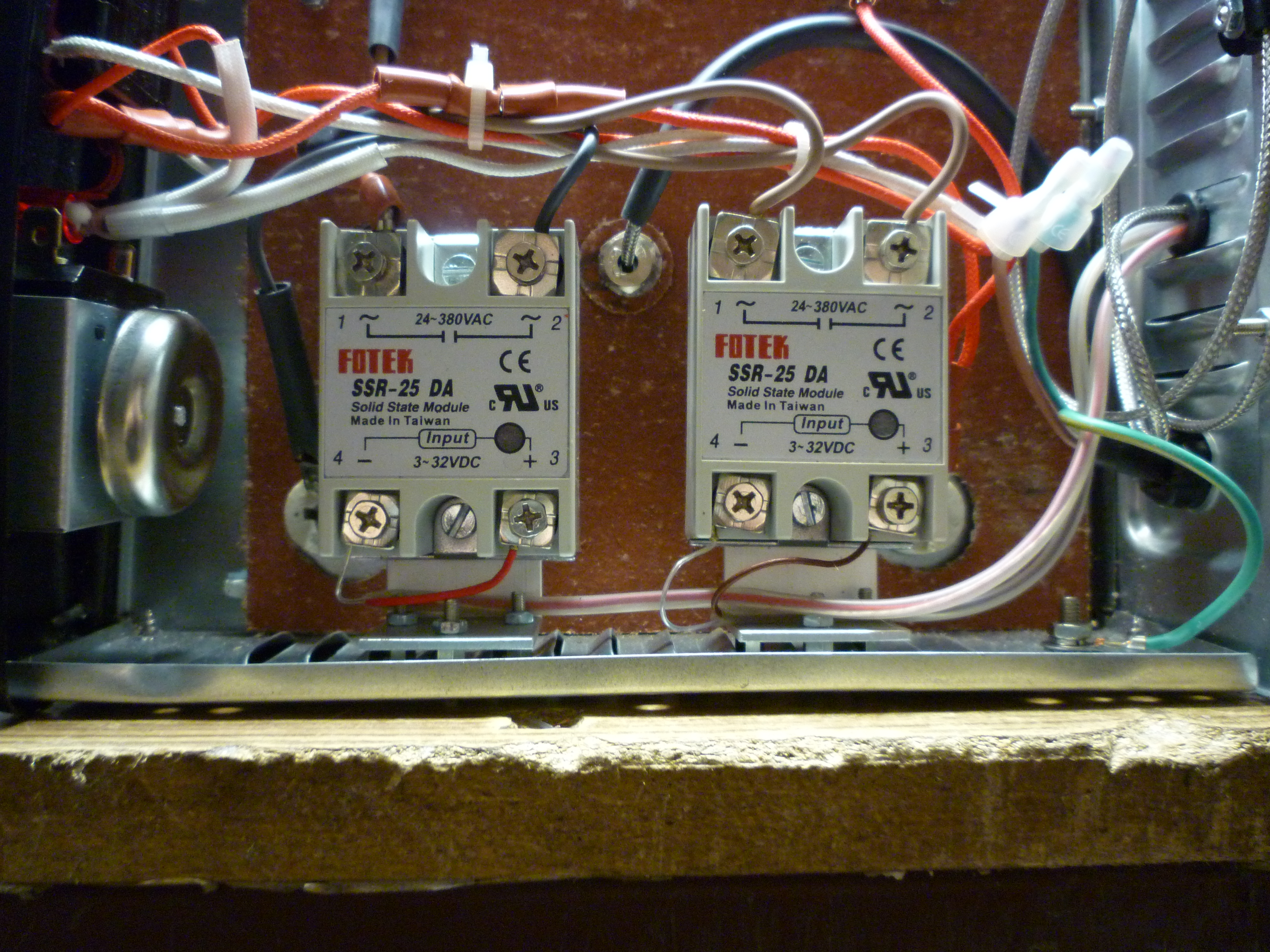
After testing the relays, there emerged a problem — it seems that altough the specifications claim that 2.4V is enough to switch them on, even at 3.3V they were still off (well, the oven was consuming around 200W, not enough to even start heating up). Luckily, this was easily fixed by connecting the anode of the relay directly to the (unregulated) 5V input and then operating the GPIO pins in open-drain mode (the pins used are 5V tolerant) thus sinking the current into the pin instead of sourcing it.
Software
Great, now my code is going to be controlling mains voltage and heating elements potetially capable of setting the house on fire. Let’s not screw up.
ChibiOS

As the STM32F030 is quite powerful (in comparison to Atmegas and the like) the opportunity to use some RTOS arises. The one I decided to use was ChibiOS. It does have all the nice things one would expect from multi-threaded environment — semaphores, mutexes, events, messages and much more. It also does have a Hardware Abstraction Layer with all the STM32F030 drivers already implemented.
uIP
Is a lightweight IP stack for small MCUs. Sadly, it is no longer being developed as a standalone project (but it was merged into the Contiki operating system) .
So as the board does have an Ethernet interface the plan is to implement an HTTP server through which the oven can be controlled.
Well, with 64kB of flash and 8kB of RAM this should definitely be doable.
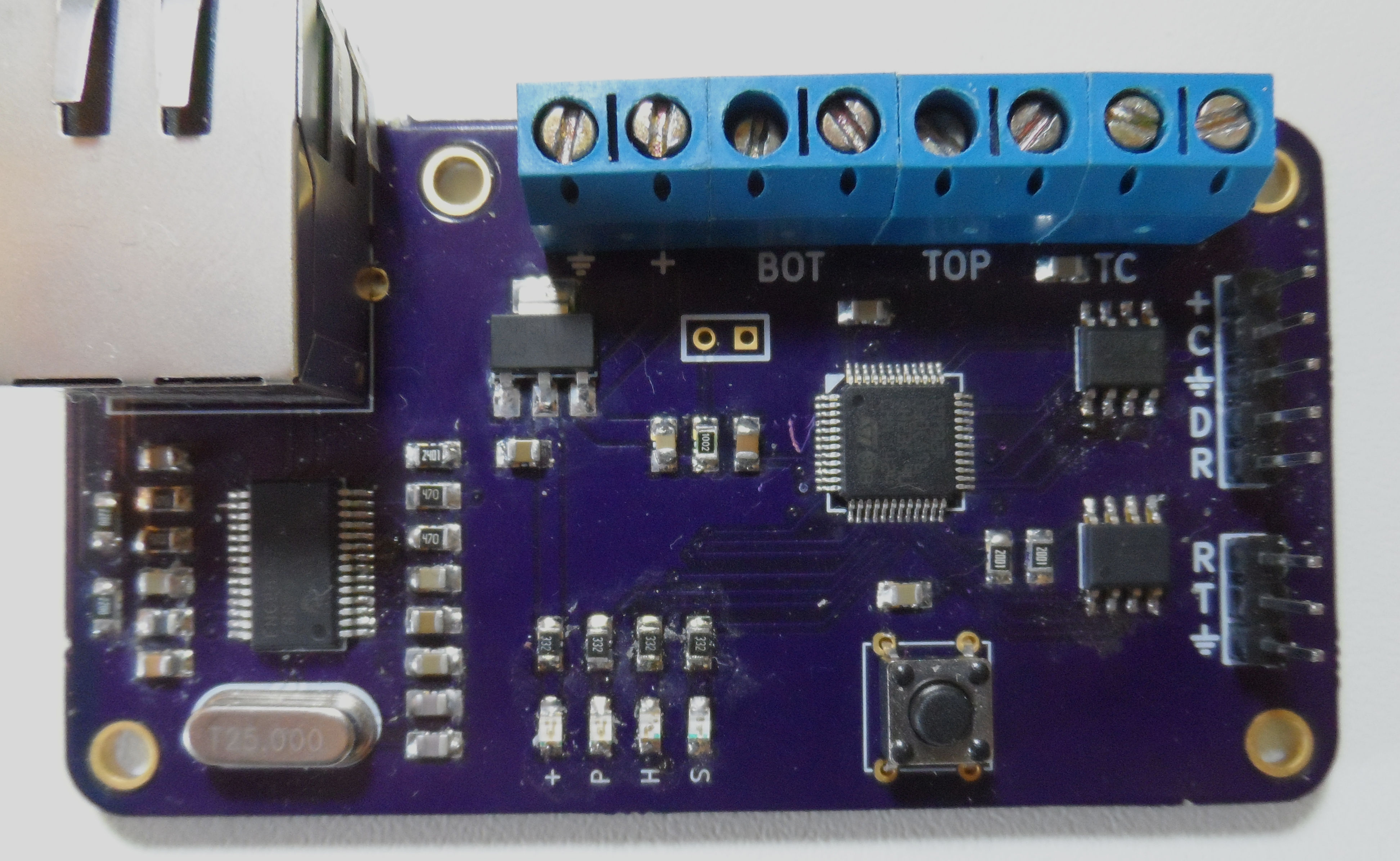
So after some time coding and debugging (I will do test pads next time, soldering 0.1mm mod wires directly to the 0.65 mm pitch pins so I can connect with my logic analyzer is somewhat of a pain). I came up with the following:
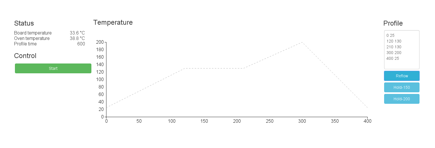

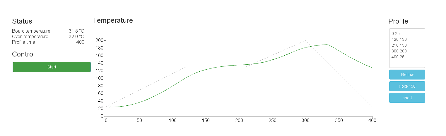
The web interface uses jQuery, the default bootstrap theme and for drawing graphs there is the really cool d3 library. To minimize the flash memory footprint, these libraries are loaded externally from CDNs (this means that the oven is, sadly, not usable without internet connection). The rest of the files are minified, then converted to C array using vim’s xxd -i, embedded into the firmware image and then served directly from the device. Even with the files included, the image still takes up only around 30kB of the flash memory from the total 64kB.
The way the interface works is simple, on the right, one enters the desired temperature profile or selects one of the predefined ones (the format being “<time> <target-temperature>\n”). Then after clicking the “Start” button, the oven starts attempting to follow the desired profile. To control the oven, the client side JavaScript logic uses AJAX.
On the MCU, there are three threads, one handles the relay control, second periodically samples the temperature and the third manages the network. I recommend you checking out the sources if you want to know more.
Testing
So after testing the thing on a few LM358

Great! Except for a few easily removed bridges on the QFP it worked and it looks much cleaner than hand soldering.
Code
You can find the code on GitHub.
The OSH project can be found here.