TWILight - VGA I²C breakout board
Some time ago, I stumbled upon an article about 25¢ I²C adapter. I usually use my Raspberry Pi to interface with I²C devices, but having it right on my notebook seemed like quite useful thing, so I decided to build a project around it.
Probing
Altough the mentioned article says that I²C is not supported on Intel cards on Linux (all of this was tested on Dell Latitude E5530 which does have Intel HD4000), I decided to try anyway. A lot has probably changed since 2008 when it was written.
$ ls /sys/class/i2c-adapter
i2c-0  i2c-1  i2c-2  i2c-3  i2c-4  i2c-5  i2c-6  i2c-7  i2c-8
Well, this means I have 9 I²C buses available on my box (with this kernel at least). Maybe there are some interesting devices already there?
$ for i in $(seq 0 8); do i2cdetect -y 1; done
...
Sadly, not much. Only device present is at address 0x50 on bus 2. This is usually SPD memory on the RAM module. There is kernel driver in drivers/misc/eeprom/ and i2c-tools userspace tool decode-dimms if you want to play with this more.
Anyway, one of the buses should be on the external VGA connector, so let’s just use logic analyzer to determine, which one it is.
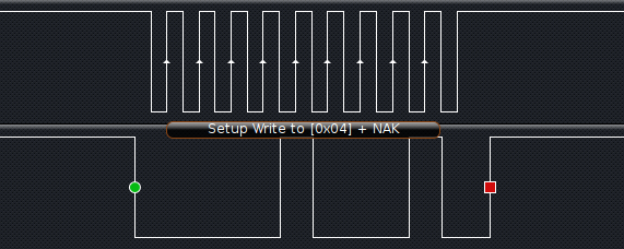
The bus number 1 turned out to be the correct one.
Board
Design
One of the problems (or features) with the built-in I²C bus is, that it does have internal 5V pull-up resistors. This is only useful as long as you do not want to talk to lower voltage devices.
Because of that I decided to make board with VGA connector and level shifter. Because I had a few Atmega328s around from previous project and they were not of any more use, I added one on the board as well to serve as a GPIO expander + LED driver. You can never do anything wrong with several LEDs.
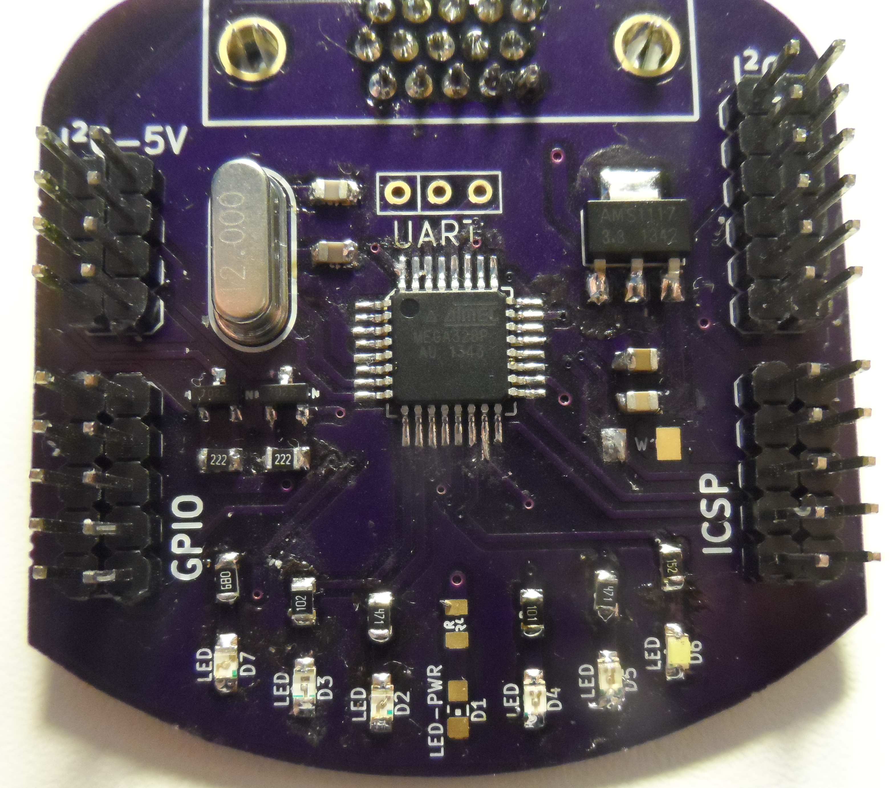
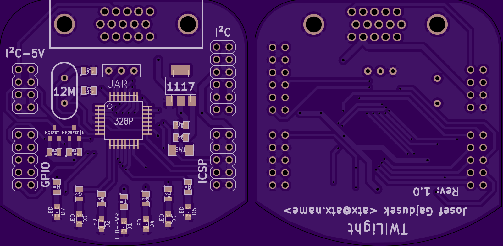
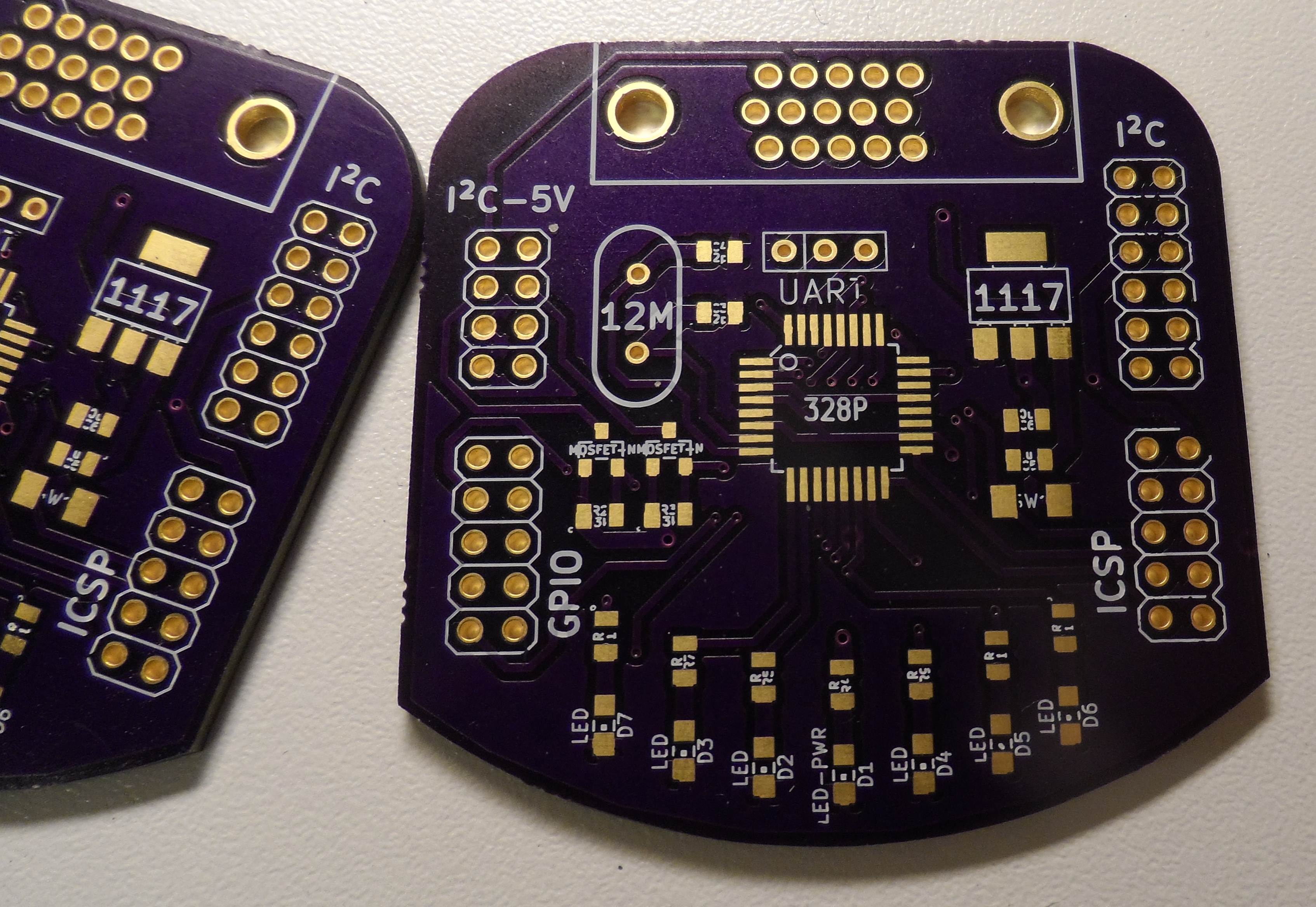
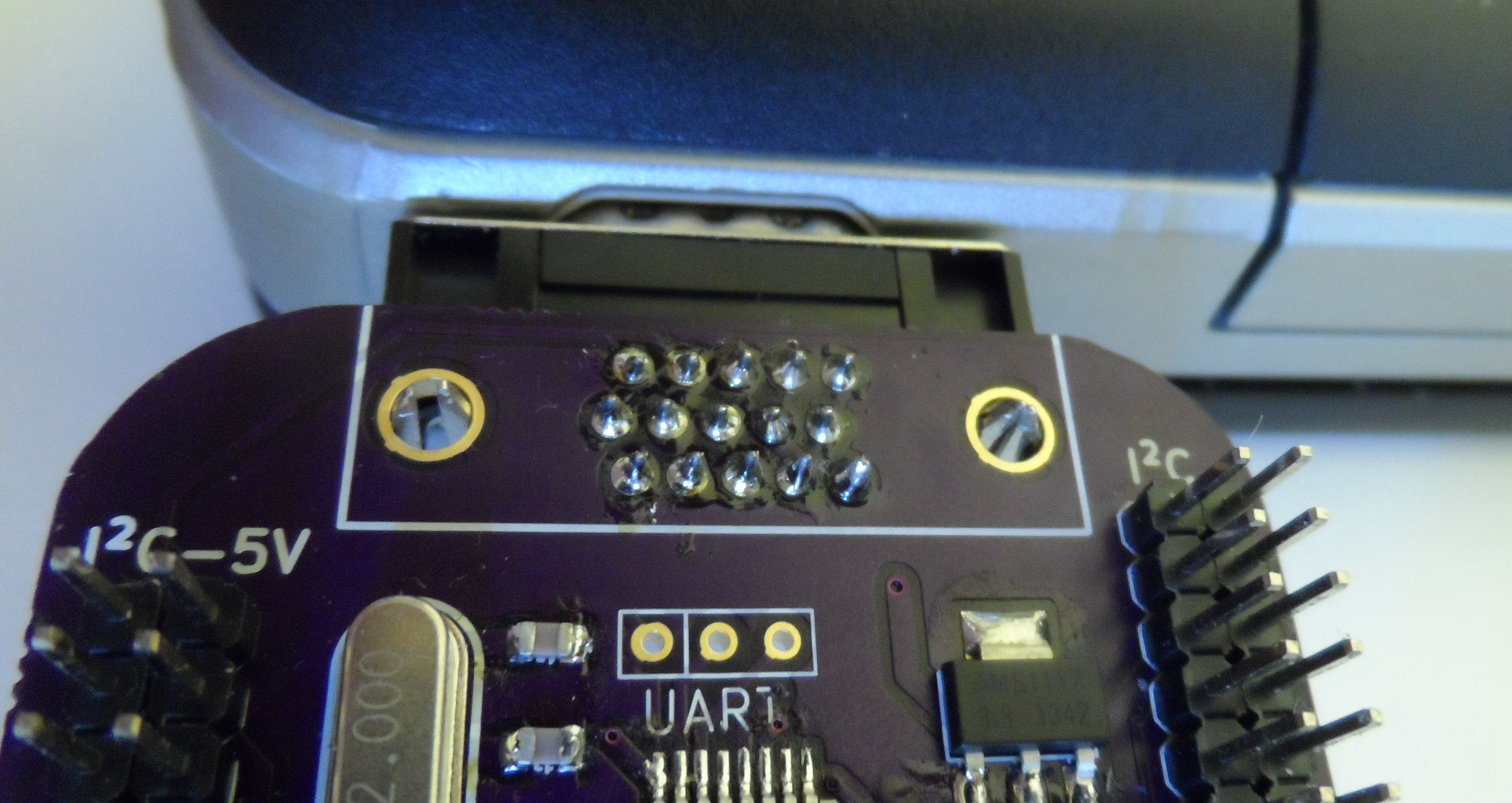
After a few hours, this was created:
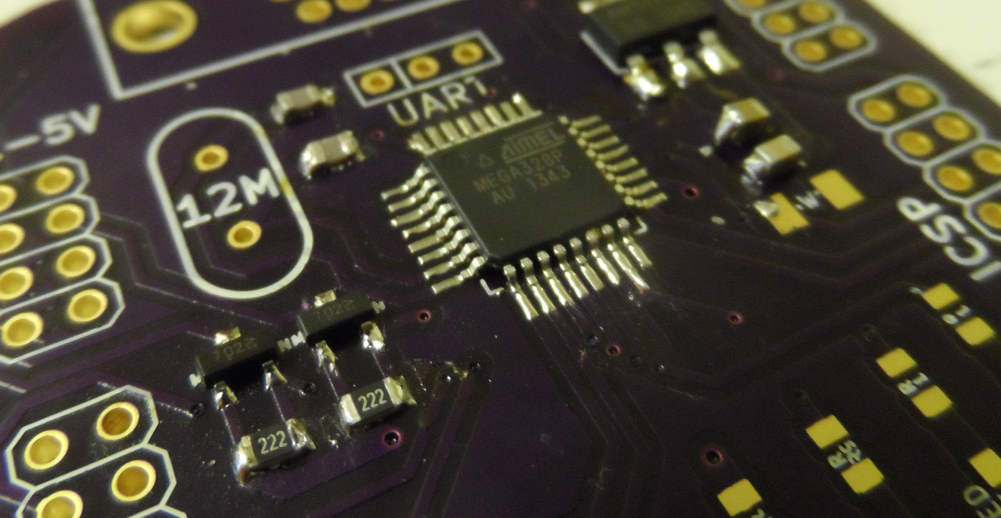
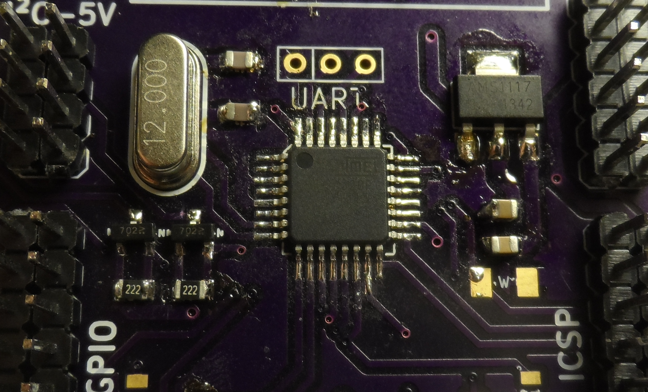
The AVR runs on 12MHz crystal (just on the edge of what it can handle at 3.3V) and does have 4 LEDs connected to its PWM channels + 10 GPIOs on one of the external headers (2 more LEDs are connected to GPIO0 and GPIO1). There is also one LED for power indication, but in the final build, this one was left unpopulated. As for the I²C, headers for both 5V and 3.3V lines are in the top left and top right. 8-pin ICSP header is used to load code into the Atmega. UART in the middle is for debugging/bootloader if that is ever needed.
Specialized ICs which can be used to level shift I²C exist, but this seemed unnecessary as you can get away with just two N-MOSFETs. See this app note for more details about I²C bus isolation and level shifting.
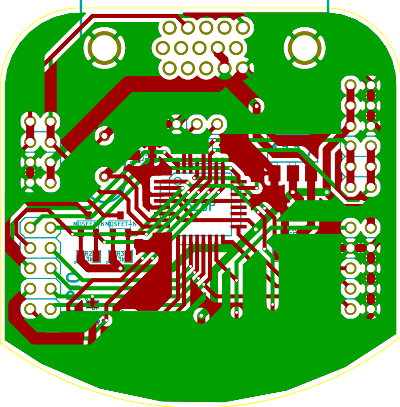
Originally, the boards were meant to be manufactured at Itead studio, but later, because of the cool purple solder mask, I went for OSH instead.
The VGA connector, MOSFETs, LEDs, voltage regulator and the crystal had to be ordered from China, because I didn’t have any suitable at hand.
Assembly
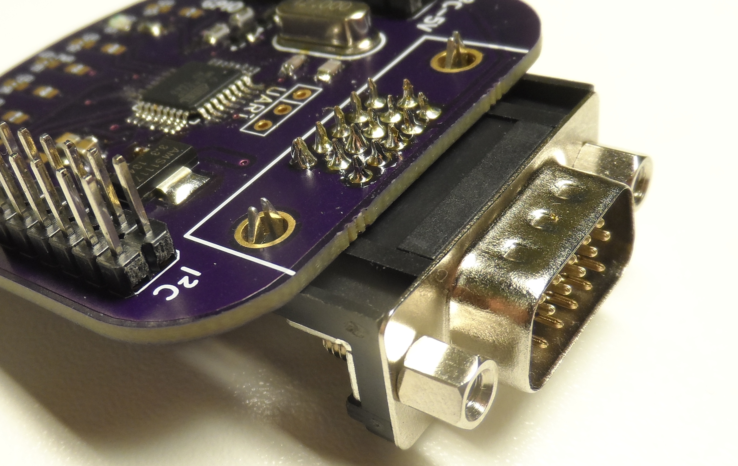
Components were slowly arriving and about a month after ordering, the PCBs arrived. There was a problem with the chinese supplier sending RS232 connectors instead of the VGA ones (did get refunded). Luckily, I could get the correct connectors ordered to local hardware store so this delayed the project only by few days.
After starting to put components in place, I noticed, that the VGA doesn’t fit from the top of the PCB but from the bottom. This was caused by wrong KiCad footprint originally made for female version of the connector (male PCB VGA connectors seem to be quite an exotic part actually). It turned out to be the only problem with the board and considering it was the third one I’ve ever designed, this went surprisingly well.
Firmware
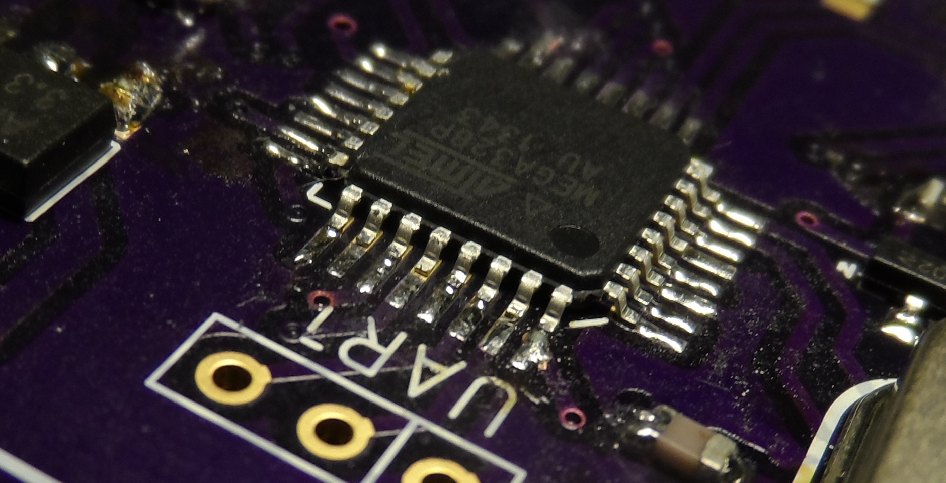
First, this Atmega is huge overkill for such simple application (especially @12MHz, but the crystal is there more to ensure stable UART communication in case it is ever needed than to get performance boost).
It just plays SMBus-compatible device with folowing memory layout:
- 0x00 - GPIO
- …
- 0x10 - LEDs
- …
- 0x14 - Magic string “ATX”
- 0x17 - Firmware version
The GPIOs map one pin per byte with following structure 00000[PIN][PORT][DDR]. This greatly simplifies driver code and allows atomic access to individual pins.
LEDs directly write/read directly from the PWM OCR registers. If 0 is written, it also disables the timer (otherwise short voltage spike would be generated at the start of each cycle).
Magic string and firmware version are there to allow some form of autodetection. This is currently not implemented in the kernel driver as it proved to be quite unreliable.
Power up & userspace testing
Now the board is assembled, so let’s plug it into the notebook and pray it does not catch on fire!
Using i2c-tools, some basic testing can be done. See if it actually is on the bus:
$ i2cdetect -y 1
     0  1  2  3  4  5  6  7  8  9  a  b  c  d  e  f
00:          -- -- -- -- -- -- -- -- -- -- -- -- --
10: -- -- -- -- -- -- -- -- -- -- -- -- -- -- -- --
20: -- -- -- -- -- -- -- -- -- -- -- -- -- -- -- --
30: -- -- -- -- -- -- -- -- -- -- -- -- -- -- -- --
40: -- -- -- -- -- -- -- -- -- -- -- -- -- -- -- --
50: -- -- -- -- -- -- -- -- -- -- -- -- -- -- -- --
60: -- -- -- -- -- -- -- -- -- -- -- -- -- -- -- --
70: -- -- -- -- -- -- -- --
And nothing… after about half an hour of playing around with multimeter, logic analyzer and oscilloscope I found out, that there was not sufficient amount of solder on one side of the QFP package. After fixing that, the AVR appeared:
$ i2cdetect -y 1
     0  1  2  3  4  5  6  7  8  9  a  b  c  d  e  f
00:          -- -- -- -- -- -- -- -- -- -- -- -- --
10: -- -- -- -- -- -- -- -- -- -- -- -- -- -- -- --
20: -- -- -- -- -- -- -- -- -- -- -- -- -- -- -- --
30: -- -- 32 -- -- -- -- -- -- -- -- -- -- -- -- --
40: -- -- -- -- -- -- -- -- -- -- -- -- -- -- -- --
50: -- -- -- -- -- -- -- -- -- -- -- -- -- -- -- --
60: -- -- -- -- -- -- -- -- -- -- -- -- -- -- -- --
70: -- -- -- -- -- -- -- --
i2cdump just reads the entire 255 byte address space of SMBus device.
$ i2cdump -y 1 0x32 b
     0  1  2  3  4  5  6  7  8  9  a  b  c  d  e  f
00: 00 00 00 00 00 00 00 00 00 00 00 00 00 00 00 00 ....?...........
10: 00 00 00 00 41 54 58 02 00 00 00 00 00 00 00 00 ....ATX?........
...
Great! The magic values are correct, now to turn on some LEDs:
$ i2cset -y 1 0x32 0x10 0xff
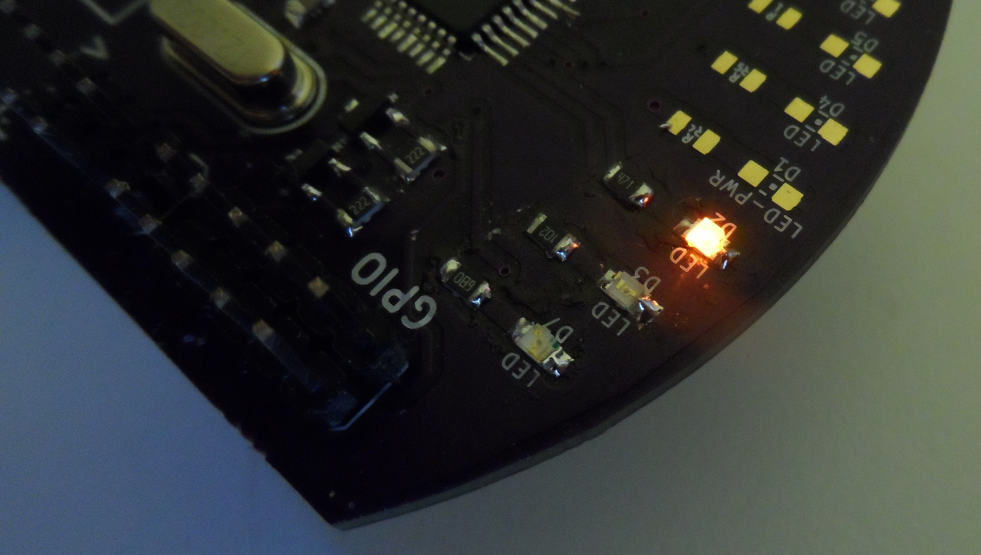
The orange LED turned on. Maybe some GPIO?
$ i2cset -y 1 0x32 0x01 0x03This seems to work too.
Onto the kernelspace!
As it turns out, the Linux kernel does not only support GPIOs, it also does have LED abstraction layer (the most pointless kernel subsystem ever (how can something so awesome as LEDs be “pointless” is beyond me though)). The I²C, GPIO and LED kernel interfaces are quite easy to speak to and there is a lot of “example” code in drivers/leds and drivers/gpio, writing driver should therefore not be big problem.
After crashing the system more times than I’d like to admit, the kernel module was done. Now i can do:
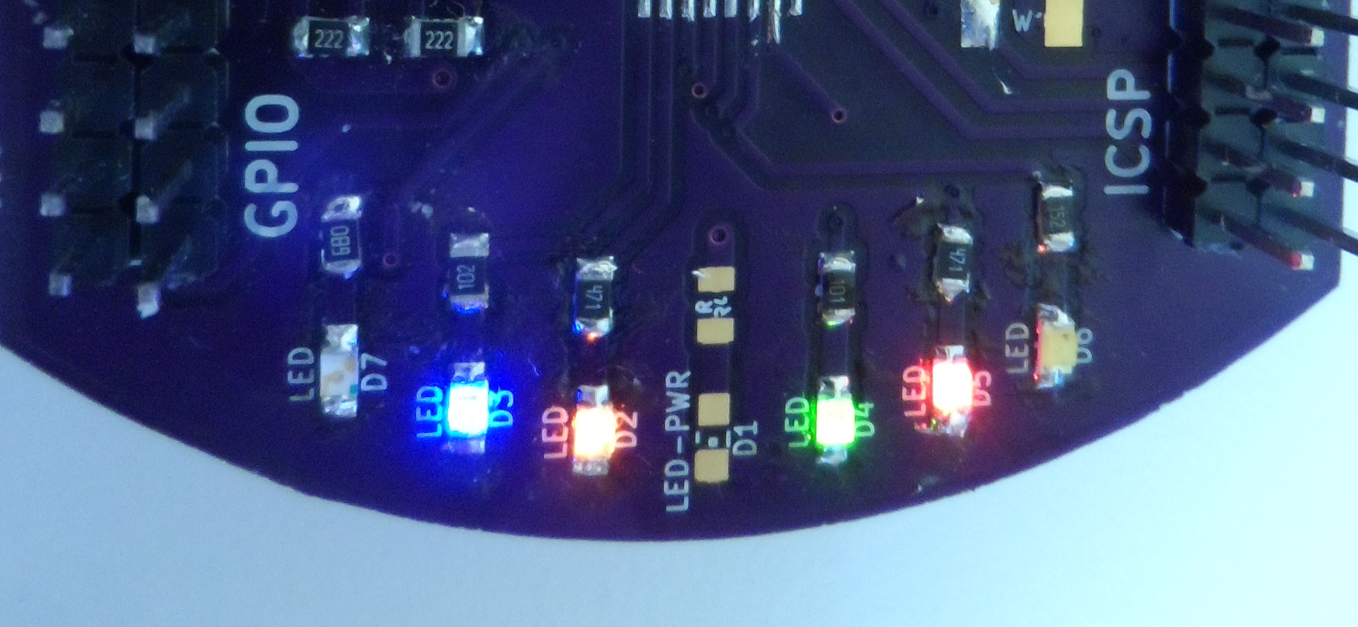
$ ls /sys/class/leds
twilight-1:blue:  twilight-1:green:
twilight-1:orange:  twilight-1:red:
$ echo 127 > /sys/class/leds/twilight-1:orange:/brightness
Or use the trigger subsystem:
$ echo heartbeat > /sys/class/leds/twilight-1:blue:/trigger
$ echo mmc0 > /sys/class/leds/twilight-1:orange:/trigger
And I also have the GPIOs:
$ ls /sys/class/gpio
export  gpiochip246  unexport
$ cd /sys/class/gpio
$ echo 247 > export
$ echo out > gpio247/direction
$ echo 1 > gpio247/value
The automatic id allocation seems to pick quite strange numbers, but it works.
There is a way to register GPIO pins as LEDs, but the x86 architecture does not have this function compiled in by default (and it is not selectable in menuconfig nor configurable in .config file). You have to add select LEDS_GPIO_REGISTER to some selected option in some included Kconfig (or create new option to toggle this setting). This is not currently in the driver as I do not like having to keep out-of-tree patches up to date with mainline kernel.
Sources
You can find repository with the KiCad PCB project, kernel code and AVR firmware on Github. OSH project can be found here