kvak - pi/4-DQPSK demodulator documentation
This page serves as documentation for kvak — a pi/4-DQPSK demodulator for our TETRA project at the brmlab hackerspace.

Note that I am by no means a DSP expert, the approaches used in this software could easily be misleading, suboptimal or just plain wrong.
This code also served as semestral project for my college intro to programming class.
pi/4-DQPSK
pi/4-DQPSK is a somewhat special variant of Phase-Shift Keying used by TETRA. The variant is a modification of QPSK, alternating between two constelations rotated by 45 degrees apart.
| Phase change | Symbol |
|---|---|
| $$\frac{\pi}{4}$$ | 00 |
| $$\frac{3 \pi}{4}$$ | 01 |
| $$-\frac{\pi}{4}$$ | 10 |
| $$-\frac{3 \pi}{4}$$ | 11 |
Notice that subtracting \(\frac{\pi}{4}\) every symbol effectively makes this into DQPSK. This will be automagically caught by the frequency recovery loop described later.
Phase and frequency recovery
The local oscillators of the receiver and the transmitter are independent. Therefore, the receiver is going to observe a phase and frequency shift from the transmitter.
A mechanism for correcting this error is required.
Error function
To figure out our phase offset, we need something to tell us how far and in which direction are we off.
Naively, we can take the angle of our input symbol and compare it with the corresponding (closest) diagonal.
\[\DeclareMathOperator{\atan}{atan} E = (\atan(\frac{i}{q}) \bmod \frac{\pi}{2}) - \frac{\pi}{4}\]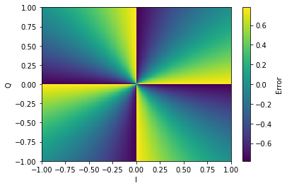
This is somewhat cumbersome, as it requires calculating \(atan\) for each sample, which would be better to avoid.
There is a trick to make the calculation computationally less demanding:
\[E = sgn(i)q - sgn(q)i\]
There is a minor issue here — the value is no longer amplitude independent. Notice that the atan-based error function has equal value on every line passing through the origin. This is no longer the case for the approximation.
This means that we need to ensure our input channels have more or less comparable amplitude.
Loop
Error calculated by the error function is fed to a feedback loop, which corrects the incoming sample stream, as per the following pseudocode:
frequency_offset = 0.
phase_offset = 0.

for input_sample in stream:
	phase_offset += frequency_offset  # Don't forget to clamp here

	# Derotate by multiplying with e^(wj)
	corrected = input_sample * expj(phase_offset)

	error = error_fn(corrected)

	# Correct the frequency loop
	frequency_offset -= error * frequency_coefficient
	phase_offset -= error * phase_coefficient
AGC
\[g[t] = w g[t - 1] + (1 - w) \left| x[t] \right|\] \[y[t] = \frac{x[t]}{g[t]}\]Here, \(g[t]\) is effectively a long term “average” of the input signal amplitude with the “weight” \(w\) dictating how quickly are amplitude changes tracked.
This part really isn’t all that critical, as we are receiving from a bunch of stationary base stations, which means there really shouldn’t be any fast amplitude transitions.
Timing recovery
We have another issue coming up - what do we do if the transmitter and receiver sample clocks do not match exactly? Realistically, this will almost always be the case! We could be receiving 2.01 or 1.98 samples per symbol.
There are multiple techniques to solve this problem.
As the input rate from our channelizer is nominally 2 samples per symbol, I picked the Gardner method.
\[e[t] = (y[t] - y[t - 1]) y[t - \tfrac{1}{2}]\](note that this is done for the I and Q components separately and the results are just summed afterwards)
\(e[t] < 0\) means we are lagging behind and \(e[t] > 0\), indicates we are running ahead.
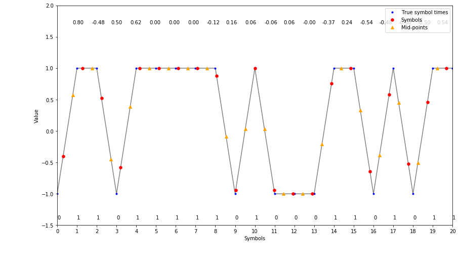
I am somewhat unsure at this point about how does this algorithm actually work — it seems “obvious” for the signal-shaped-as-triangles case, however Tetra (and most other PSK systems) shape the symbols using the raised-cosine filter, which does not have zero crossings at the midpoint between the samples.
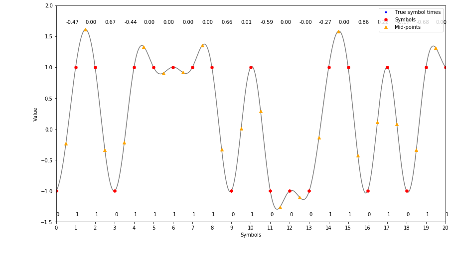
Notice that the symbols are sampled perfectly, yet there is non-zero error!

Presumably, we could argue by symmetry and proclaim that these errors will average out over time (given slow enough feedback loop).
Timing recovery “pseudocode”
The timing recovery process is illustrated by the almost-python code below:
# Effectively says how many output samples we get per one input sample
resampling_fraction = 1.
# Our current position in the input stream
time_pointer = 0.

input_samples = [0.] * 8   # 8 sample long buffer
output_samples = [0.] * 3  # 3 sample long buffer
midpoint = False
while True:

	while time_pointer <= 1.0:
		output = resample(input_samples, time_pointer)
		output_samples.append(output)

		# Move the pointer forward
		time_pointer += resampling_fraction

		midpoint = not midpoint
		if midpoint:
			continue

		# Apply Gardner TED to the last 3 samples
		error = gardner_ted(output_samples[-4:-1])

		# Update the loop state
		resampling_fraction -= error * integral_coefficient
		time_pointer -= error * proportional_coefficient

	# Fetch the next sample and move our pointer backwards by one sample
	input_samples.append(get_next_sample())
	time_pointer -= 1.
Output from detector is fed to a PI loop, which attempts to track the timing error.
On fractional resampling
Our timing recovery is able to tell us whether we are sampling too fast or too slow. However, we need to close the feedback loop somehow. To do this, let’s implement something called fractional resampler.
As our input, we have a series of samples, now we need to figure out what is a value of an “in-between” sample. A powerful fact at our disposal — the input samples were sampled without violating the Nyquist criterion.
Naively, this means that we can interpolate our signal by some relatively high interpolation factor and then just pick the intermediate sample that we need. This would of course be unnecessary, as we don’t really need all the in-between samples.
To interpolate a discrete-time signal, we have something called the Whittaker-Shannon interpolation formula. This is effectively convolving a time-axis shifted sinc function with our input samples in order to calculate a sample at any in-between point of the signal.
\[\DeclareMathOperator{\sinc}{sinc} x(t) = \sum_{n=-\infty}^{\infty} x[n] \sinc(t - n)\]Filter design
There are several technicalities to be solved now — calculating the formula from definition would demand convolution with infinite-length filter and it also requires us to compute the sinc value for any of the in-between points we obtain.
First, let’s split the intra sample space to, say, 128 discrete points and just round to the closest one when interpolating. This will effectively introduce sample clock jitter to our signal, but it’s something we can live with. Second, let’s limit the length of the filters to some reasonable amount of taps, say, 8. These parameters are used by GNURadio, so they are probably a good enough starting point.
At this point, we need to get N filters, shifting the signal in the 0-1 sample period interval. This PDF introduces several methods to get these filters — I went with the easy one — that is taking the sinc function, shifting and windowing.
\[\DeclareMathOperator{\sinc}{sinc} h_D[n] = w(n - D)\sinc(n - D)\]Where
\[\begin{align} D \in & \, \{ \frac{0}{128}, \frac{1}{128}, \dots, \frac{127}{128}, \frac{128}{128} \} \\ n \in & \, \{-3, -2, \dots, 3, 4\} \end{align}\]And \(w(t)\) is some window function. My implementation uses the hamming window, but there is no specific reason for this choice.
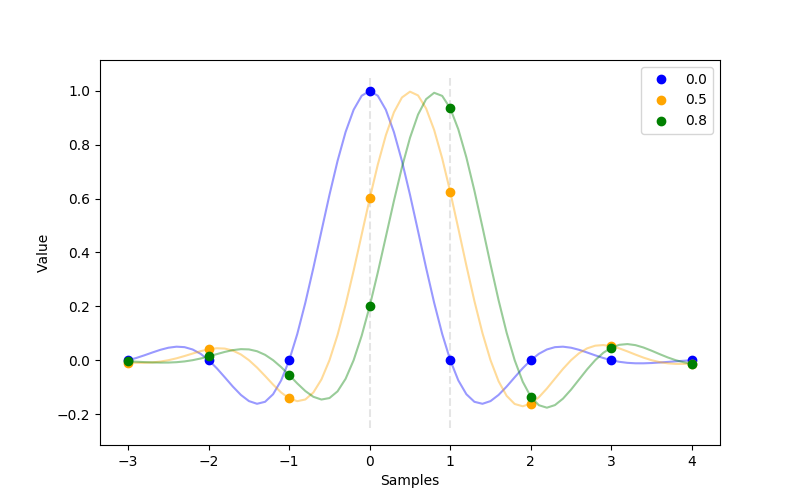
There are methods which get “better” filters, using iterative methods, such as the one implemented in GNURadio. I am not sure how big of a difference would these improved filters make.
Figuring out coefficients for the PI loops
At this point, we have 2 PI loops, requiring 4 coefficients. PI loop coefficients are somewhat of a dark magic though.
Anyway, I hacked together a genetic algorithm script which attempts to explore the coefficient space maximizing the amount of valid frames received as reported by OsmoTETRA (pro tip — build tetra-rx with -O3 to get a 6x speedup!).
Usage
In our setup, data from the channelizer is fed to a Unix FIFO. Output from the demodulator is then fed to another set of FIFOs, which are finally fed to tetra-rx from osmotetra
$ kvak -i /var/run/tetra/fcl/1.ch -o /var/run/tetra/kvak/bits.1.%d.ch -n 20Control
The demodulator exposes a capnproto-based RPC interface.
The repository includes a command line interface to interactively control the demodulators.