Importing pinouts from PDF tables to KiCad
One of the most annoying parts of PCB design is definitely creating all the schematic libraries. To make this task easier, I decided to at least partially automate the extraction of pinouts from datasheets. As more complex MCUs can have over a hundred pins, this can speed up the time it takes to build the symbol considerably.
1. Extract the pinout table from the datasheet
There are multiple tools which are able to do this, I personally use Tabula.

Note: For ST datasheets, select “lattice” as the extraction method
From the table in the datasheet, Tabula produces .csv, which after some cleanup looks like this:
$ sed -i 's/\r//g' tabula-stm32f7.csv
$ head tabula-stm32f7.csv
Pin Number,"","","","","","","Pin name (function after reset)(1)",epyt ni,"ucturerts O/I","",Alternate functions,"Additional functions"
"FP100 LQ","SP143LCW","FP144LQ","671AGBFU","671PFQL","208PFQL","216AGTFB","","","","","",""
1,D8,1,A2,1,1,A3,PE2,I/O,FT,-,"TRACECLK, SPI4_SCK, SAI1_MCLK_A, QUADSPI_BK1_IO2, ETH_MII_TXD3, FMC_A23, EVENTOUT",-
2,C10,2,A1,2,2,A2,PE3,I/O,FT,-,"TRACED0, SAI1_SD_B, FMC_A19, EVENTOUT",-
3,B11,3,B1,3,3,A1,PE4,I/O,FT,-,"TRACED1, SPI4_NSS, SAI1_FS_A, FMC_A20, DCMI_D4, LCD_B0, EVENTOUT",-
Pin Number,"","","","","","","Pin name (function after reset)(1)","n typei","reut strucIO/","",Alternate functions,"Additional functions"
"FP100 LQ","SP143LCW","441PFQL","176AGFBU","FP176LQ","FP208LQ","216AGTFB","","","","","",""
4,D9,4,B2,4,4,B1,PE5,I/O,FT,-,"TRACED2, TIM9_CH1, SPI4_MISO, SAI1_SCK_A, FMC_A21, DCMI_D6, LCD_G0, EVENTOUT",-
5,E8,5,B3,5,5,B2,PE6,I/O,FT,-,"TRACED3, TIM1_BKIN2, TIM9_CH2, SPI4_MOSI, SAI1_SD_A, SAI2_MCK_B, FMC_A22, DCMI_D7, LCD_G1, EVENTOUT",-
-,-,-,-,-,-,G6,VSS,S,-,-,-,-
2. Generate KiCad .lib
For this part I wrote a small python library which is capable of generating KiCad .lib files. There is a generic script in the repository, which kind of works as long as the input .csv is reasonably formatted.
$ head -n 5 tabula-PCA9535.csv
INT ,1 ,22 ,interrupt output (open-drain)
A1 ,2 ,23 ,address input 1
A2 ,3 ,24 ,address input 2
IO0_0 ,4 ,1 ,port 0 input/output[2]
IO0_1 ,5 ,2,""
$ csvtokicad -i tabula-PCA9535.csv -o pca9535.lib -n PCA9535 -k "{1}" -p "{0}"
 1 	-- INT
 2 	-- A1
 3 	-- A2
 4 	-- IO0_0
...
22 	-- SCL
23 	-- SDA
24 	-- VDD
PCA9535 saved to pca9535.lib
If the script is not good enough (as in the STM32F7 case, where the pins need to be split by banks), the library can be quite easily used directly:
#! /usr/bin/env python3

import re
import csv
from eeschema import *

lib = SchemaLib()
com = Component("STM32F745xZA", nparts = 9)
lib.add_component(com)

partrest = 1
partsgpio = {"A": 2, "B": 3, "C": 4, "D": 5, "E": 6, "F": 7, "G": 8, "H": 9}

with open("tabula-stm32f7.csv") as inp:
    reader = csv.reader(inp)
    yo = 0
    for row in reader:
        try:
            pnu = int(row[2])
        except ValueError:
            continue
        part = partrest
        pin = row[7]
        fns = row[11].replace(",", "/").replace(" ", "")
        if not fns in ["", "-"]:
            fstr = "{1}/{0}"
            if pin[0] == "P":
                fns = fns.split("/")
                fns.remove("EVENTOUT")
                if not fns:
                    fstr = "{0}"
                bank = pin[1]
                part = partsgpio[bank]
                y = -int(re.match("\d+", pin[2:]).group(0)) * 100 - 100
                fns = "/".join(fns)
            pna = fstr.format(pin, fns)
        else:
            pna = pin
        if y == None:
            yo -= 100
            y = yo
        com.add_pin(Pin(pna, pnu, x = 0, y = y, orientation = Pin.LEFT, part = part))
        y = None
        print("% 3s : %d\t-- %s" % (pnu, part, pna))

lib.save("stm32f745xz.lib")
This produces nicer results and needs much less further work in the editor.
3. Build the footprint
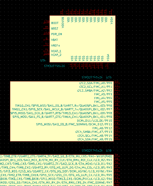
Now we can open the .lib in KiCad eeschema library editor and build the footprint from the imported pins.
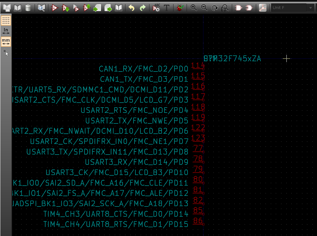
After some rearranging, the parts are ready to be used: