AVR board with MQTT support
MQTT
MQTT is a messaging publish/subscribe protocol targeted to embedded systems originally designed by IBM. For a simple overview of the protocol, I recommend the mosquitto man page or if you want, you can read the full specs here.

Broker
There are several MQTT brokers available. For my setup, I have Mosquitto running on my Raspberry Pi. (Note: If you use Raspbian, I recommend building from source - the version in repositories is outdated and misses among other things the python3 API)
The Project
I wanted to jump on the bandwagon of IoT and build some more generic platform which could be used in home automation.
Board
Choice of components
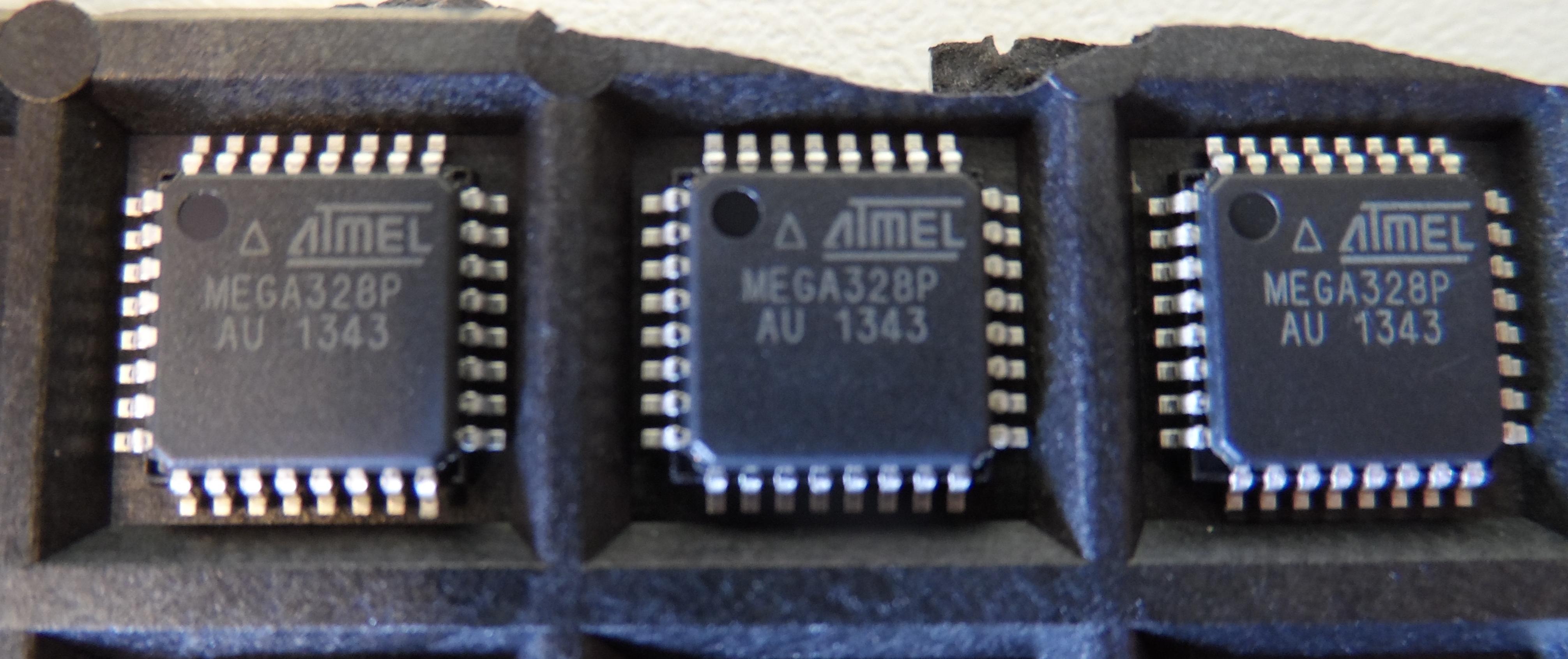
MCU - ATmega328p
I already used this AVR in my previous project (and in a few other not published ones), but have not reached its full potential by a longshot. I still had a few pieces left, so I decided to use it again. At least this time, use of such (relatively) powerful microcontroller was justified.
Ethernet - ENC28J60
Is a fairly popular Ethernet controller for small micros. It communicates with the master controller using SPI. The IC also does have several extra features, for example it is able to output its (divided by programmable prescaler) clock signal on the CLKOUT pin, it does have two configurable LED outputs and it can do hardware interrupt on WoL packet.
Another option would be the WIZ5100 which is used on the official Arduino Ethernet shield. Because this chip does have hardcoded TCP/IP, using it relieves a lot of work from the master. The only problem with this choice is the price and the fact that it seems to be slightly harder to get than the previous option.
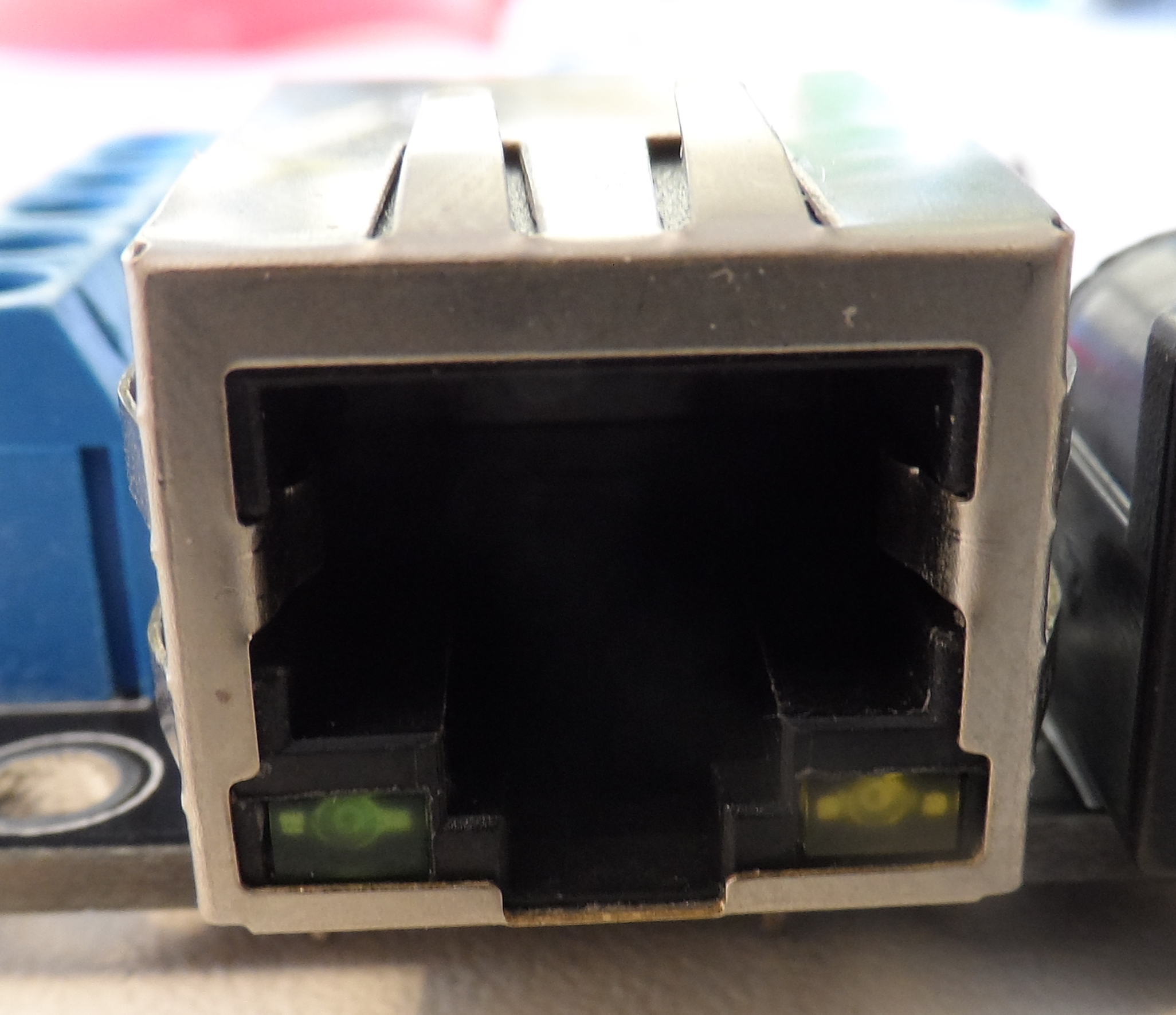
Magjack - J0026D21BNL
Because the Ethernet specs require it, pair of isolation transformers is needed on the differential TX/RX lines of the connection. You can either get separate RJ45 connectors and transformers, or there are Ethernet connectors (called magjacks) which do have these integrated inside the chassis. Using separate transformers just wastes a lot of board space (however, it seems to be a bit cheaper), so I went for the latter option. The J0026D21BNL I chose also does have orange and green LEDs built into the connector body.
Temperature sensor - DS18B20
This one is classic. Of all sensors I considered, the DS18B20 does definitely have the best price/accuracy ratio. The only problem is, that it uses the Maxim 1-Wire protocol which is not supported in hardware by my MCU of choice. Bit-banging it is fairly easy, so this did not affect the choice much. Another nice thing about these sensors is, that they are available in waterproof metal containers.
Humidity sensor - DHT11
Another very popular choice. These go for around 1$ on eBay, and do have reasonable specs. There is also sort of thermometer included, but the accuracy (+-2°C) is too low for this application.
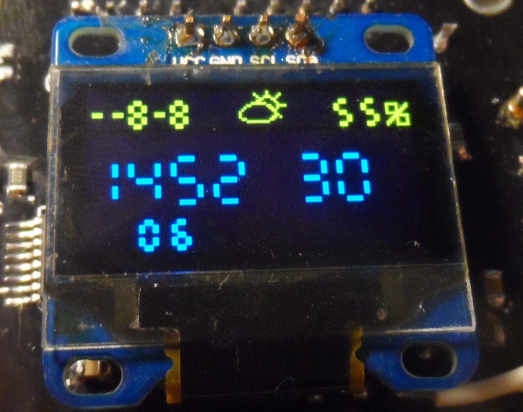
Output - .96” OLED with SSD1306
I had this one laying on my desk for around half a year and I wanted to finally use this really cool looking piece of technology. In this project, the I²C version of the breakout board is used (branded as Heltec).
There are also footprints for the LMT87 thermometer and the MS5637 barometer on the board, but I have not ordered these from Farnell yet, so they are unpopulated in all my builds and there is no support for them in the firmware.
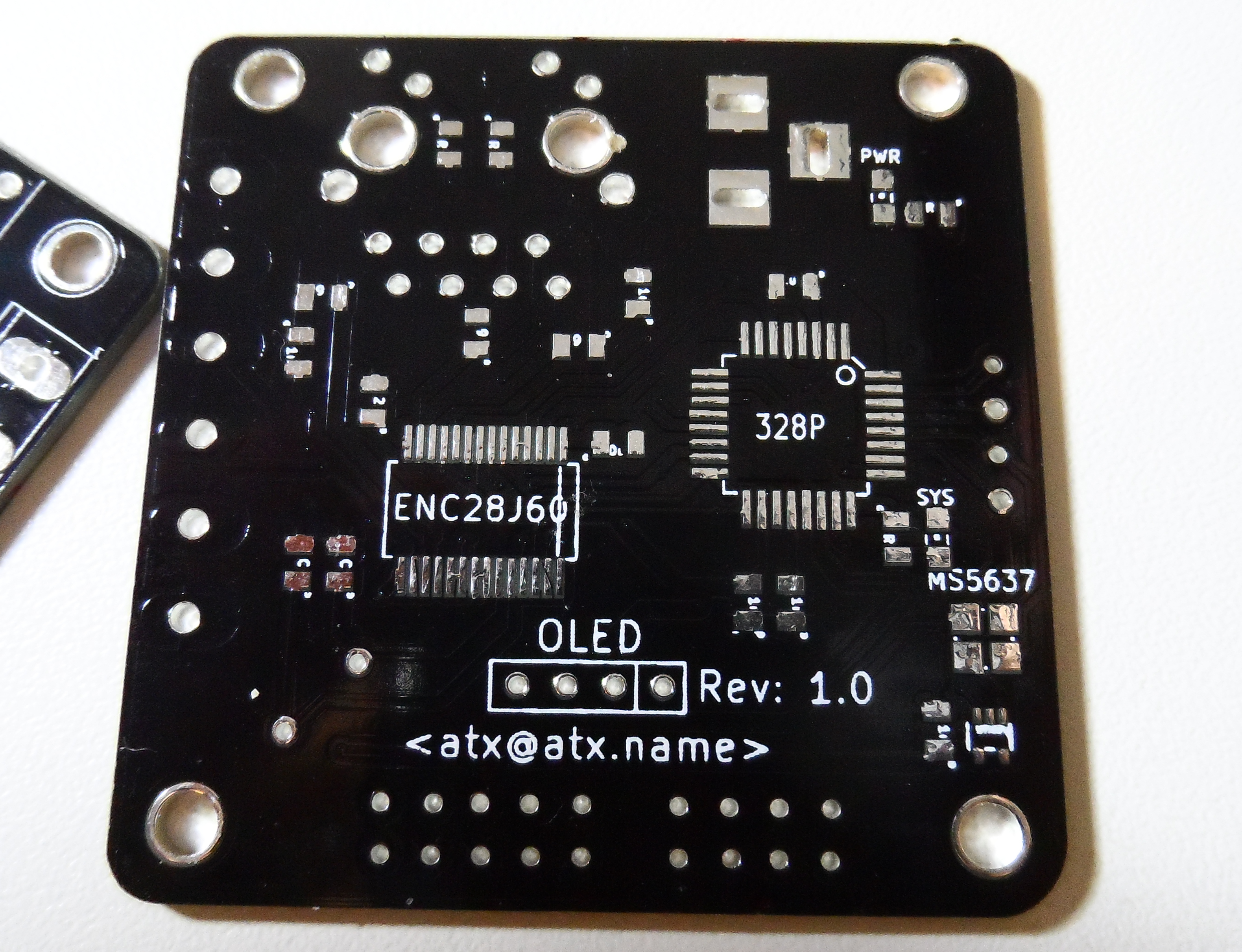
Design
After some time of staring at KiCAD and reading datasheets, I came up fairly simple design:

The AVR is clocked from the Ethernet controller - on powerup at 6.25MHz which is later increased to 12.5MHz (I also tried running the AVR on the full 25MHz, it works. I would not count on it being stable though). The entire board can either be powered directly by 3.3V on the ICSP header, or through a barrel jack connector which is connected to an AMS1117 linear voltage regulator. Two GND, two +3.3V and two GPIOs are brought out on screw terminals - these are supposed to be connected to the DHT11 and DS18B20 sensors. The rest of the free IO is on a standard 2.54mm header. In total, there are four LEDs, two on the magjack, connected directly to the ENC28J60, one tied to the +3.3V line and one controlled by the AVR.
Bill of Materials
| Name | Amount | Price |
| ATmega328P | 1 | $ 1.4 |
| AMS1117 | 1 | $ 0.1 |
| ENC28J60 | 1 | $ 1.9 |
| J0026D21BNL | 1 | $ 1.45 |
| OLED | 1 | $ 6.85 |
| 2.1mm Barrel Jack | 1 | $ 0.3 |
| 2x1 Screw Terminal | 3 | - |
| 2.54mm Pin headers | - | - |
| R 49.9 1% | 4 | - |
| R 2k32 1% | 1 | - |
| R 1k8 | 2 | - |
| R for LEDs | 4 | - |
| C 10uF | 2 | - |
| C 1uF | 2 | - |
| C 100nF | 6 | - |
| C 100nF | 6 | - |
| 5x5 PCB</a> | 1 | $ 1.5 |
| $ 12.0 |
Please note, that I bought most of the parts in bulk, so the whole project cost me more that the per-board total here.
Build
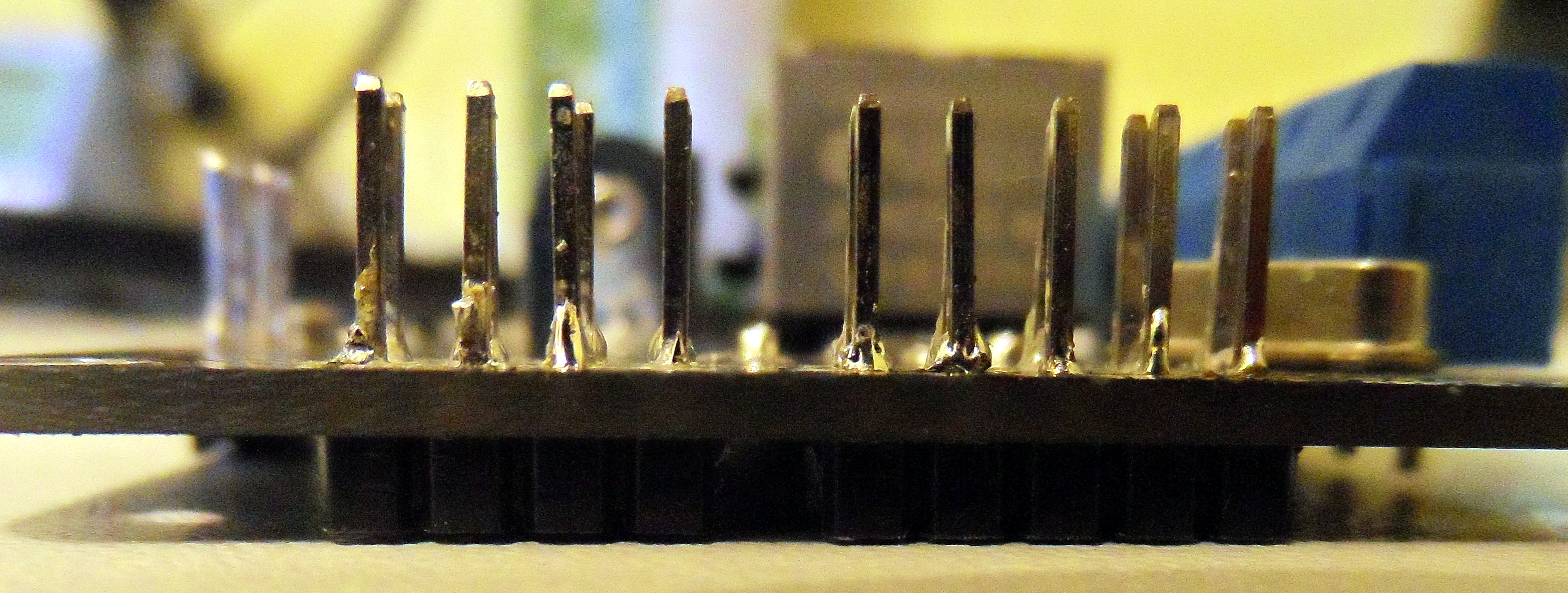
When the boards arrived from DirtyPCBs, I noticed, that most of the through-hole pads had solder mask over them on one side. At first, I thought that this was manufacturing defect. Then, I checked the gerbers and it turned out, that the library used for the connector footprints had the pins masked only on one side. After a while of attempting to solder onto the coated side (I actually managed to solder one board this way, it works but looks somewhat ugly), I just solved it this way:
Also, I did not have the correct values of resistors around - partly because I made a mistake when ordering and partly because the local components supplier did not have the rest in stock. Instead of the 2k32R 1% resistor I used 2k40R and instead of the 49.9R termination ones, I have 47R. Despite this deviation from the datasheet, everything seems to work flawlessly.
After finishing the first board and plugging in the network, I noticed something strange - none of the LEDs connected to the ENC28J60 lit up. The LEDA and LEDB outputs of the chip are quite configurable and on power up, they should light up when there is a physical connection established even without any master intervention. It took quite some time pondering over the schematic and measuring, but then I figured, that there is missing connection between the +3.3V power line and the center tap of the transmit coil. Luckily, this could be fixed by adding short jumper wire between one of the screw terminals and the pin connected to the center tap.

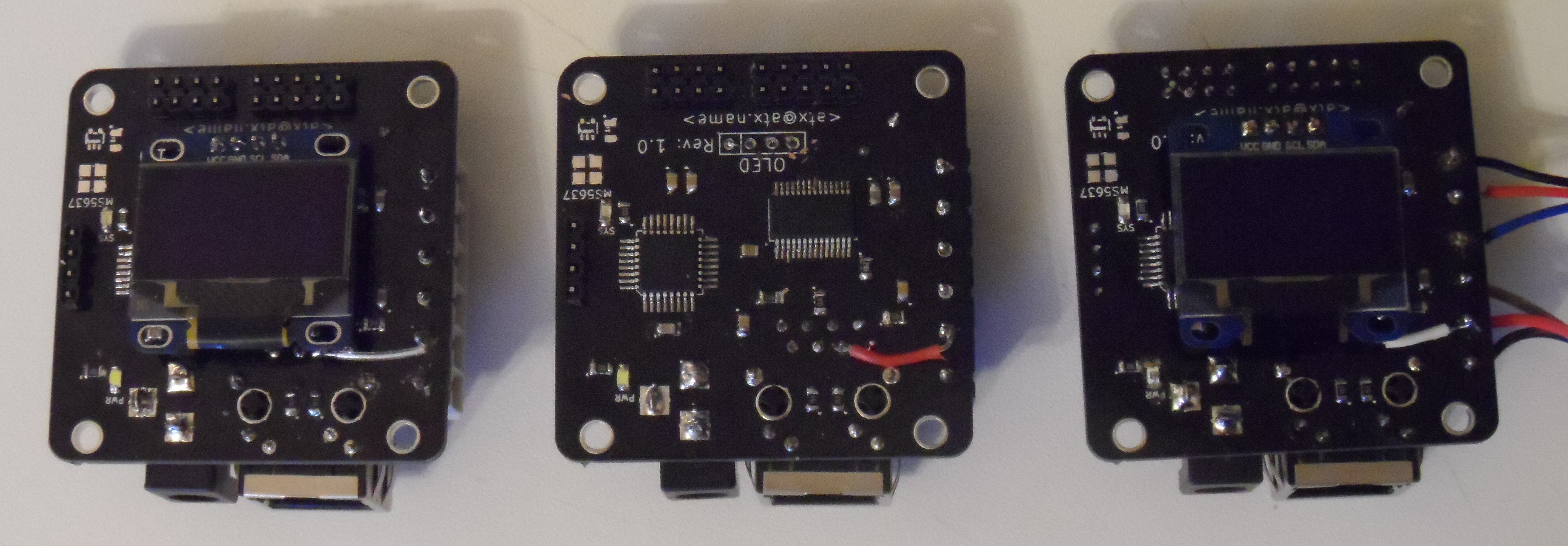
Ultimately, I ended up building three boards, one as solder paste+hot air soldering exercise (I am actually surprised about how much thermal abuse can the Ethernet controller withstand while still being functional) and the other two using standard soldering station.
Case
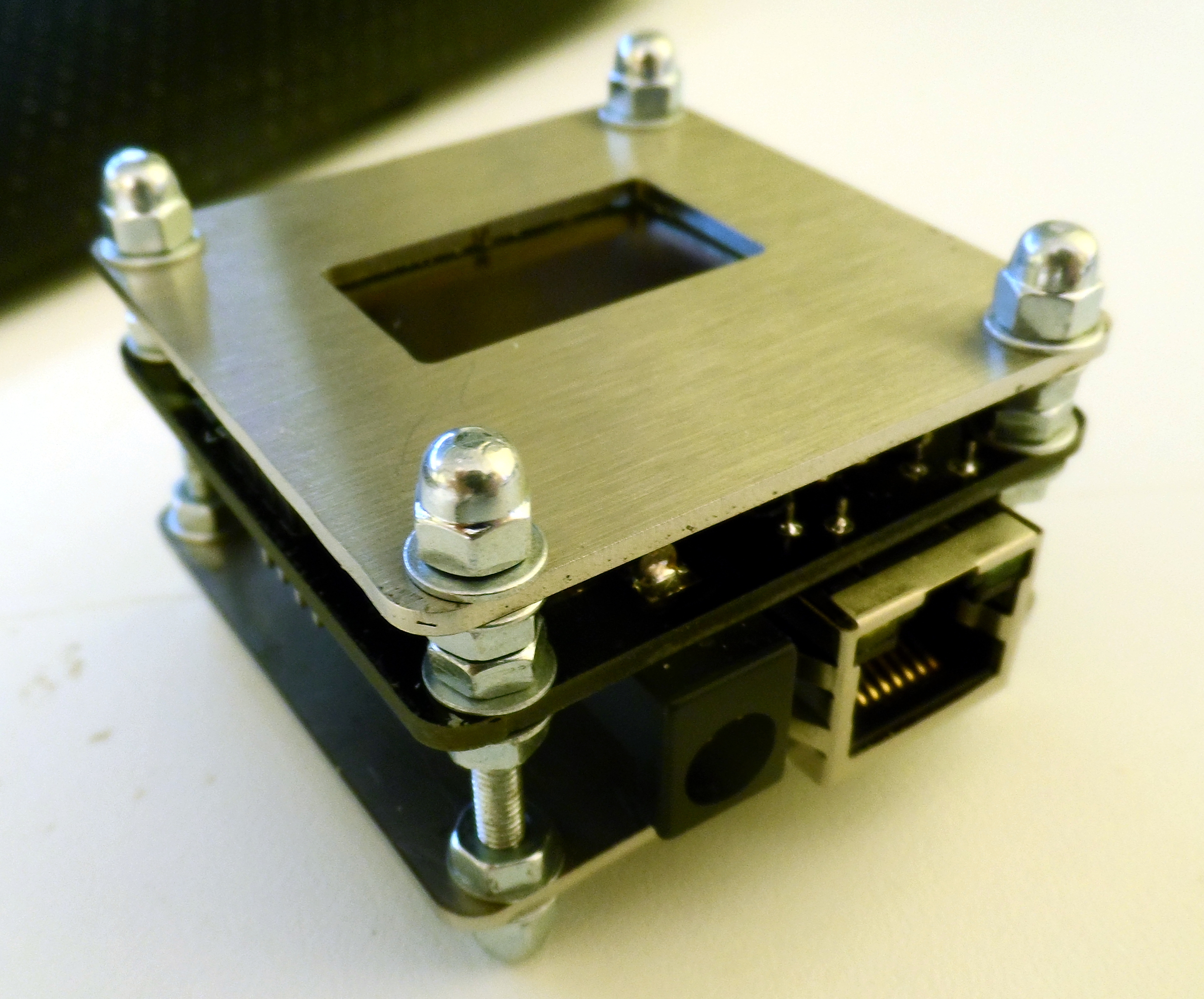
I decided to take advantage of having access to industrial laser cutter and make an enclosure for the board. The drawing (enclosure.dxf in the repository) was made using LibreCAD
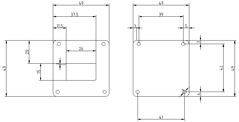
and the two plates themselves are laser cut from 1.5mm thick stainless steel. To get the correct length, the bolts were cut from 3mm threaded rod.

Software
The TCP/IP stack used is AVR-uIP (AVR port of the original uIP). Sadly, the port seems to have died in 2012. My branch which contains few minor modifications can be found on GitHub but as I plan to base more of my future project on ARM, I would not rely on this being maintained in any way.
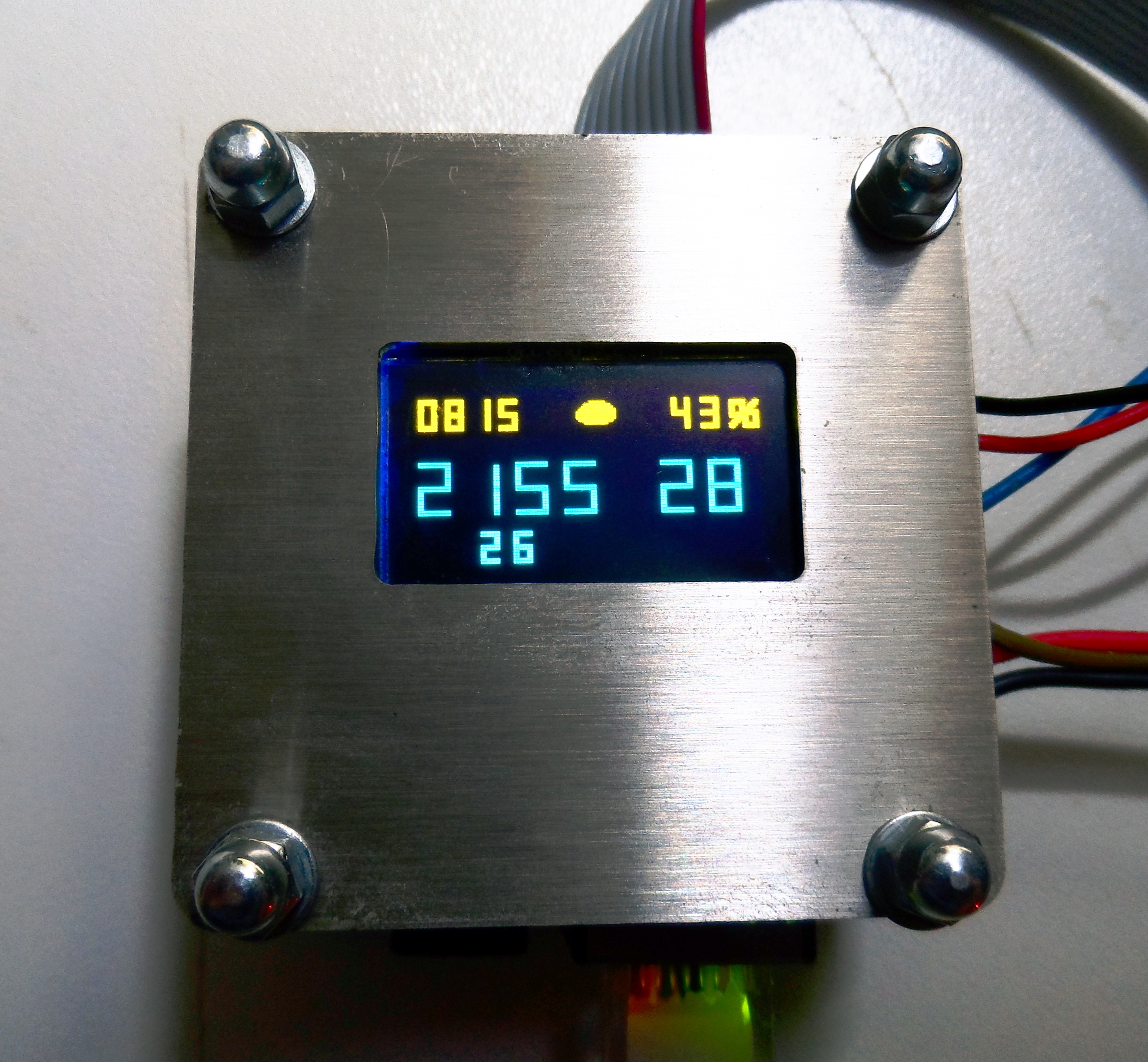
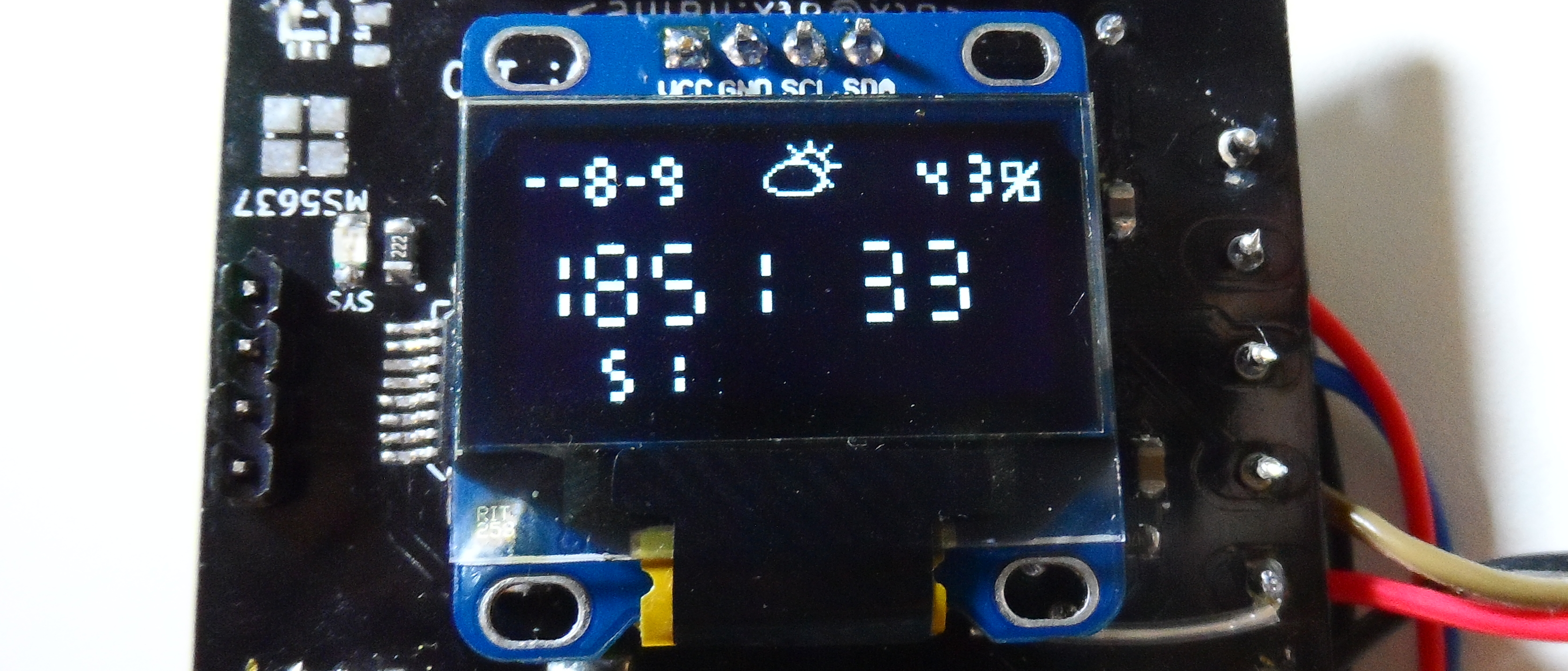
OLED
The OLED displays:
- Current time
- Current date
- Weather forecast
- Measured temperature
- Measured humidity
The driver code is few months old and based on example Arduino code sent to me by the display manufacturer. Because of historical reasons, it bit-bangs the I²C protocol. I might rewrite this in the future (the board design does account for this possibility), but it works reasonably well for now.
To convert images to C arrays, I wrote the tooled.groovy script which can be found in the utils directory in the git repository.
MQTT
For the MQTT client library, I wrote my own uMQTT. This is IP-stack independent and should be quite simple to port to anywhere you want. For usage example, see the nethandler.c file.
Used MQTT topics (con be configured in config.h):
time/date
I have cron job, which publishes retained ASCII date here every day:
0 * * * * /usr/local/bin/mosquitto_pub -r -t "time/date" -m "$(date +\%Y-\%m-\%d)"time/daytime
Another cron job. This time it posts time every five minutes. Note that the time is in the local time zone - this allows for elegant centralized handling of summer time.
*/5 * * * * /usr/local/bin/mosquitto_pub -t "time/daytime" -m "$(date +\%H:\%M:\%S)"sensors/temperature/frontdoor
Every SENSORS_PUBLISH_PERIOD, the current temperature in millidegrees C is published here.
sensors/humidity/frontdoor
Every SENSORS_PUBLISH_PERIOD, the relative humidity percentage is published here.
weather/local/general
The device subscribes to this topic and watches for a set of ASCII strings (cloudy, lightning, rain, snow, clear+cloud, clear). It then displays pictogram on the OLED corresponding to the weather forecast. I use this script to fetch weather from the OpenWeatherMap API and publish it to this topic every hour.
Sensor drivers
The code for both the DS18B20 and the DHT11 is very minimalistic. All it does in both cases is read the sensor value. No 1Wire abstraction or addressing in case of the DS18B20 and no CRC/temperature reading in case of the DHT11.
IO
The IO exposed to the world is also declared in the config.h:
#define BUTTONS \
	BUTTON(C, 3, "input/button/doorbell/top"), \
	BUTTON(C, 2, "input/button/doorbell/bottom")

#define OUTPUTS \
	OUTPUT(C, 0, "output/binary/bell")
For the buttons, the AVR sends the string “pressed” to the defined channel every time the associated GPIO pin is pulled low. The pins do have activated the internal pull-ups and are software debounced.
The outputs react to “true”/”false” being sent to their corresponding topics and set the GPIO pin high/low.
Application
As you might have already deduced from the topic names above, the primary application was smart sensor station which could also watch the doorbell and be able to manually ring the bell (there is no press button -> ring bell software logic — I figured it would be more fail-proof to have the buttons hardwired to the bell). To further integrate MQTT to my usual setup, I also wrote a simple IRC bot which works as MQTT->IRC bridge. This means, that whenever someone presses the button at the front door, I get an IRC message.
Source
The repository containing the pcb schematic and the code can be found on GitHub
If you want to build the firmware, do not forget to run git submodule update --init to fetch the dependencies.